I think it would be difficult to come up with a way to turn the MOSFETs on with a non-isolated voltage source, remember the MOSFETs gates must be made a few volts more positive than the source terminals to turn them on, so the driving circuit will be connected to whatever is being switched, so if one of the drains is at ground, then the common source terminals cannot be grounded. I think in the long run it's just easier to use the optoisolator.
Whoops, I just noticed in post #211 I said drive voltage is between gate and drain, should be between gate and source, I should know better than to try to use my brain early in the morning. 🙂
Whoops, I just noticed in post #211 I said drive voltage is between gate and drain, should be between gate and source, I should know better than to try to use my brain early in the morning. 🙂
Other factors that affect contact reliability and life of relays is the heat capacity and thermal resistance of the contacts themselves, and the surrounding ambient temperature. Inside power amplifiers the operating temperature can be +55 degrees or more. I am not surprised that relays in some power amplifiers fails after just a few years.
Other factors that affect contact reliability and life of relays is the heat capacity and thermal resistance of the contacts themselves, and the surrounding ambient temperature. Inside power amplifiers the operating temperature can be +55 degrees or more. I am not surprised that relays in some power amplifiers fails after just a few years.
I think this is especially true when concerning the relay itself which will dissipate a certain amount of heat within the coil. The relay cases were always warm to the touch and I bet the temperature internal to the relay was quite a bit hotter then that. Still the temperature shoul be low when the amplifier is first turned on and when turned off, hopefully the music has stopped by then!
Relay I pulled from a protection board. Most of what you see on the bottom 3 contacts are reflections so aplogies for the poor photo. In short all 6 contacts are in perfect condition.
This relay did about 10 years of almost daily service between a 150W amp with +/- 60V rails and a woofer. It's a common DPDT FRM3W-2B10 rated at only 10A @24V. I run both halves in parallel so I guess that ups the rating to 20A.
It never had to cope with a major amp failure but with switch on incidents and the like DC detection would have tripped it a few times.
There are interesting and easy ways to set the relay up to have a higher innitial potential to switch the relay and then reduce it to just high enough to keep the relay in that state. This should help with the lifespan, if things are getting fried due to heat, which I am not buying yet. I suspect most relays die due to arching and gets welded stuck. Even gold contacts are not a defence against this, as I found out welding an expensive Finder relay shut on first power up once.
I could be quite wrong, but I have it in my mind the whole problem comes down to contact wear is worst when breaking a current.
Almost all relays have the contacts mounted where at least one side is on a flexible strip. This generally ensures a wiping action. This wiping action "cleans" the contacts on closing.
I further add a coil current reduction circuit that overvolts the coil and reduces the running current to approximately half the nominal coil current. This overvolts exaggerates the wiping action as well as ensuring faster closing (and probably excessive bounce) but on reducing the coil current the contacts move back over the previously wiped region to finally settle in a "clean" area. These little tweaks do not stop nor do they reduce contact wear at opening.
I could be quite wrong, but I have it in my mind the whole problem comes down to contact wear is worst when breaking a current.
I think that's absolutely correct... and breaking of current create an arc.
Like you I overvolt my relays at switch on. 220uf cap charged to higher than relay coil rating ensure a smart action when powered up via a schmidt type trigger. There's no ramping of the coil volts. And like yours, it then reduces to around 50 % of nominal.
I experienced audible distortion though as you probably read,
http://www.diyaudio.com/forums/solid-state/191449-output-relays-9.html#post2646972
I've seen examples of the relay contacts being bypassed by small value capacitors to prevent arcing. At the moment the contacts open the capacitor is empty, so the current has a path to take just long enough for the contacts to get far enough apart to prevent arc-over. I've tried it myself and it really does a good job of suppressing any arcing of the relay contacts.
an old fashioned car ignition Inductor + Capacitor + switch are exactly what you are describing. The auto industry tried in vain to reduce the switch contact wear. Eventually the only way to avoid contact wear was to remove the mechanical switch to be replaced with a Solid State switch.I've seen examples of the relay contacts being bypassed by small value capacitors to prevent arcing. At the moment the contacts open the capacitor is empty, so the current has a path to take just long enough for the contacts to get far enough apart to prevent arc-over. I've tried it myself and it really does a good job of suppressing any arcing of the relay contacts.
If the relay never breaks a high DC current, then as per the spec sheets, you can generally expect 100k operations. Mechanically, many commonly available relays can do a million operations. So Andrew is quite correct. It is indeed the breaking of DC current that causes the problems.
If the relay never breaks a high DC current, then as per the spec sheets, you can generally expect 100k operations. Mechanically, many commonly available relays can do a million operations. So Andrew is quite correct. It is indeed the breaking of DC current that causes the problems.
Hi Bonsai,
99% of the time mine have never broken anything current wise. The remaining 1% would be only a few hundred milliwatts at most. I always make a point of never having music playing while powering up or down... but I suffered this effect (audible distortion). It's in a clean room, no smoke or pollution of any kind.
It is the sort of problem that I would always say "happens to someone else" but it hasn't.... it's happened to me 🙂
Yes I would say exactly the same thing. Of course the amplifier will have been turned on and off occasionally when playing music, but nothing particularly loud and again after the active xover.
When I first set the protection up I did do some testing, this didn't including having it break large loads of DC. The problem looks like something that has crept upon me over time and I've never had an amplifier fail.
Whatever the mechanism is that's caused this is, doesn't really matter, the solution is simple enough, don't use relays!
Additionally the only thing I can think of are the occasions when the circuit breaker at the fuse box has tripped causing the active xover to turn abruptly off. As there is no output muting in the active xover a large bang/pop gets sent through the amplifier, this causes the protection to trip. This has only happened a handful of times mind you and the relay damage looks like something that's built up slowly over time rather then being destroyed 10% per shock.
I just popped the top off of the other 5 relays. Out of the 6, only 2 showed signs of damage, the other 4 were absolutely fine. Interestingly the relays that had been damaged had nothing in common. One was on a tweeter with a high cut off frequency in the DC detection and one was on a midrange that had full range detection. One was on the left channel and one was on the right.
I'm undecided and sticking with my monster DC relays (KUEP series)
The problem is interrupting high current DC with significant series inductance. This principle is used in arc welders... but doing some math with 5.1mH speaker+xover inductance, a 75VDC/8ohm fault is about 224mJ of avalanche energy for the mosfets.
PVI's have an internal depletion-mode mosfet (IRF AN1017) to speed up switch off times, PVI5013 is 0.25msec@200pF and the Avago ASSR-V622 seems much faster: 0.03msec@1000pF (I'm not sure why the LED current spec is not zero).
Low Rds on mosfets have high capacitance and I would expect them to take longer to switch off under avalanche due to Ciss.
The IRFS3607 is rated for 120mJ avalanche over 0.04msec single-pulse, so more than one is needed but with Ciss=3,072pF each I think they would get beat up during a fault due to slow switch-off times.
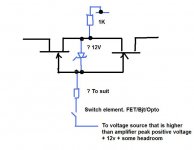
Firstly let me just say the photovoltaic method seems ideal... but I wondered about this.
It's the same FET arrangement but drive for the FET's is from a fixed voltage source derived from say a doubler off the PSU. The current could be in the milliamp or less range so easy to implement.
The FET has Vgs limited to whatever the zener is chosen to be.
The 1k (not even sure it's needed) is to allow the switch to initially close. I think if a load were connected it wouldn't be needed as the zener current would flow either into the amp or load via the internal diodes in the FET's
The drive for the FET comes from a source higher than the max output of the amp plus the zener volts. So no matter what the output of the amp is (- rail or + rail), the drive voltage is significantly higher and the FET's are always on. Maybe a constant current diode rather than a resistor would be better. Also a high value resistor across the zener to define an "off" condition i.e. never floating. The zener hold Vgs constant.
Any thoughts... 🙂 Would it work ?
Attachments
Hi Mooly,
Looks like it may be workable, I might have the parts on hand to give it a try. It would be a lot cheaper to do it that way than using the optoisolator.
MIke
Looks like it may be workable, I might have the parts on hand to give it a try. It would be a lot cheaper to do it that way than using the optoisolator.
MIke
I probably won't get to it until tomorrow, there's company on the way over here, and barbecuing in the works. 
Mike
Mike
Firstly let me just say the photovoltaic method seems ideal... but I wondered about this.
...or perhaps putting the SS relay in the speaker ground return as Bonsai suggests in post #61 may be simpler?
Last edited:
Maybe... 🙂
I think many want a SS relay that will physically fit where the original is though with no PCB redesign work. That's the beauty of the photovoltaic design. You can make a drop in replacement.
Mines a bit more complex to implement (if it works), but could retain the original relay placement.
I think many want a SS relay that will physically fit where the original is though with no PCB redesign work. That's the beauty of the photovoltaic design. You can make a drop in replacement.
Mines a bit more complex to implement (if it works), but could retain the original relay placement.
...or perhaps putting the SS relay in the speaker ground return as Bonsai suggests in post #61 may be simpler?
I use DPDT relays and cut both lines to the speaker.
- Home
- Amplifiers
- Solid State
- Output Relays