Maybe you can design it as a longer board so that the front end could be 'cut off' and separated if needed but if you don't need to separate it off the whole pcb can still operated as a single pcb ?
That's what I did with my KrellKlone design a while back, and splittng them wasn't really a big issue.
I may split the front end board off completely and make it as a separate PCB, and mount it above the output board.
🙂 just for inspiration
Attachments
You've actually got me thinking now, I may split the front end board off completely and make it as a separate PCB, and mount it above the output board. Then I could spread the OPs over the whole length of the heatsink...
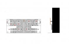
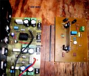
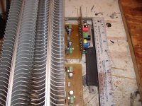
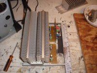
It (the idea) has been "played with". Pass's amps have that universal voltage stage. So do these (below 1) is the old way.. uses too much valuable space , good for the R-D amp 😀 . ( below 2) could be adapted to the end of a power board (outputs/drivers/Vbe/decoupling-conditioning) at a right angle or even be adapted to" piggieback" (parallel boards with the right bends to the wirewrap pin strip in the first picture. The wire wrap pins get tightly screwed to the euroconnectors , so no wiring. That 250W of AB power is in just 200 X 230mm square- 100mm high (1/5 cu. ft. pix 3). The AKSA 55 can be put on a tiny 85 X 50mm module , mine are 75x100mm. NO WIRING required , just 6 screws to tighten. Interface is just 6 connections (-V/-D/grnd./NFB/+D/V+).
OS
Attachments
ah, I was just reminded of the breakable output board, to make for 1-2-3-4 output pairs
ought to be possible
ought to be possible
ah, I was just reminded of the breakable output board, to make for 1-2-3-4 output pairs
ought to be possible
Anything is possible. 😉
Seriously folks, I wasn't planning on making any sort of production run of these boards, as it's Hugh's IP, and I only need two, so it'll be homebrew toner transfer for me. That's why I'm trying to stick to single sided, as double sided would make the layout much easier. However, if Hugh is agreeable, I will post all the Eagle files up here so people can modify them as they like.
Al,
I'm happy with that, much appreciate your work. The original AKSA was single sided, so your choice is no big deal and should be fine.
Cheers,
Hugh
I'm happy with that, much appreciate your work. The original AKSA was single sided, so your choice is no big deal and should be fine.
Cheers,
Hugh
It (the idea) has been "played with"
Indeed, and I've done it, as I said earlier. 😉
Pinkmouse and others,
I've just come across this thread. Been off playing on the dark side (Hollow State) for a while.
I was one of Hugh's Beta Testers for the AKSA55N and then N+ mods. A couple of comments on the your PCB layout.
1) Do make provision for emitter degeneration resistors on the Input LTP. Even very small degeneration resistors (I used 4R7) will improve the sound particularly if you then up the LTP current a little to recover lost gm. That will also help drive Cdom.
2) One of the things Hugh and I tried about 4 or 5 iterations off, before abandonning it was a current source load for the VAS. If you want to know where the "magic" in this amp comes from I can tell you that large lumps of it are directly due to the VAS Bootstrap - certainly the CCS loaded VAS just did'nt have the same "magic".
3) make provision for a largish cap for the bootstrap cap - its quality makes a heap of difference, also a little larger value I though sounded good, I ran a 330uF Muse for a while but eventually (since I had more money than sense that week) I ended up with 2 "Super E" connected 100uF Blackgate Ns. Make space on the PCB to accommodate at least a 330uF Muse.
4) The LTP Rail Cap also affects sonics (Rubycon ZL were good but the ZLH less so). If you have a heavy wallet then a Blackgate Standard was best.
5) The Vbe bypass cap which early schemetics in this thread did'nt show also affected the sound. Best results were using a common garden variety nonpolarised electrolytic only surpassed when I went to a Blackgate NX.
5) I see that you have included the output devices base charge "suck out" cap - good idea, this cap went thru' Ceramic to Polyester to Polypropylene as the amp was "tuned".
More I should not say - maybe said to much already.
I have some seriously lovely tube amps now but my AKSA55N+ will always be on my shelf as a reference amp.
Cheers,
Ian
Hi Ian
Thanks for your comments. I will get back to this soon, but at the moment life and finances are being a little troublesome, so it's been on the backburner for a while. I still really need the amps though, so it will get done! 🙂
Thanks for your comments. I will get back to this soon, but at the moment life and finances are being a little troublesome, so it's been on the backburner for a while. I still really need the amps though, so it will get done! 🙂
Pinkmouse and others,
1) Do make provision for emitter degeneration resistors on the Input LTP. Even very small degeneration resistors (I used 4R7) will improve the sound particularly if you then up the LTP current a little to recover lost gm. That will also help drive Cdom.Cheers,
Ian
That's interesting but my preference is to do the exact opposite. I also use far more degeneration than a few ohms too. A degeneration of 10x gm for example will enable you to reduce the value of Cdom by 10x (for the same stability margins) but with the added benefit of 10x higher slew rate.
The quest for ultimate noise figure is not the only quest.
VHF man,
Its been a while since I checked this thread.
I agree that much higher degeneration resistors in the diffamp emitters is technically (theoretically) better - having said that, my experience was that smaller (< = 10% degeneration) sounded "better". A situation where my ears told me one thing and the oscilloscope/distortion analyser/theory told me something different. I went with the ears.
Of course I'm one of those guys who generally likes their music coming out of hot glass envelopes (I like my sand on the outside) so that needs to be taken into consideration. What suited my ears may not suit everyone elses.
Cheers,
Ian
You have been so quiet... I'm almost ready to make noise. 🙂
An externally hosted image should be here but it was not working when we last tested it.
You have been so quiet... I'm almost ready to make noise. 🙂
hi Sound_Buster,
Looking good, very good.
regards
Morning all. Nice work S_B. Is that your own design of protection board in the middle?
Must get on with this, the speakers have been sitting in my front room for ages. I was temporarily distracted by the idea of going Class D, but budget won't allow ATM, so it's back to the big pile of BJTs sitting in the workshop. Will fire up Eagle in a bit and see where I got to, I honestly can't remember! 🙂
Must get on with this, the speakers have been sitting in my front room for ages. I was temporarily distracted by the idea of going Class D, but budget won't allow ATM, so it's back to the big pile of BJTs sitting in the workshop. Will fire up Eagle in a bit and see where I got to, I honestly can't remember! 🙂
Sound_Buster,
Very nice, very typical of my initial layouts, except I put them elegantly on a piece of cardboard....
Pinkmouse,
You really should scale up the AKSA, you will find you can tune it very nicely...
Cheers,
Hugh
Very nice, very typical of my initial layouts, except I put them elegantly on a piece of cardboard....
Pinkmouse,
You really should scale up the AKSA, you will find you can tune it very nicely...
Cheers,
Hugh
You really should scale up the AKSA, you will find you can tune it very nicely...
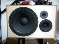
Yeah, just been sorting though all my bits and pieces. Got traffos, PSU caps and plenty of trannies. Looking ATM like two standard babyAKSAs for mid and high, and the scaled up jobbie for bottom end. Mid/high are 4Ohm, so I will experiment to see if I can get extra windings on the 45-0-45 500VA traffo so I don't need to buy more. If I can get 25V rails that should do nicely.
Attachments
Is that your own design of protection board in the middle?
Hi, P.
The layout, yes. It´s based on this circuit, with subtle differences:
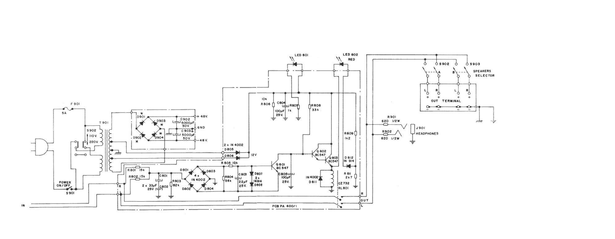
Rgds.
- Home
- Amplifiers
- Solid State
- Based on Hugh Dean's AKSA 55