Hi homemodder.
I only bought 5 of each from RS. As far as I can tell, they are good transistors.
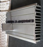
I built Dr. Bora's Sigma Amp: http://bas.elitesecurity.org/SIGMA-Schematic.pdf with them. The Sigma amp sounds good & I guessed that is what matters.
The parts are E-grade, I measured the Hfe: C3601 ~ 130, A1407 ~ 150.
I guessed that the stock at RS will not last very long given that On-semi now owns Sanyo and the main applications for these transistors are:
· Ultrahigh-definition CRT display.
· Video output.
· Color TV chroma output.
Attached is a picture.
Cheers, Stanley
After magnifying your pic to better see the details on those parts, I can say they are genuine. I would buy them all at that price, 😉
capacitance multipliers
Os
Many people do not realise that with capacitance multipliers, that the choice of main electro has an audible effect on the SQ, especially if low ESR, or Audio Grade types are used. For that matter, the same applies with the main electros in the JLH, even the 100uF output capacitor!
Alex
Os
Many people do not realise that with capacitance multipliers, that the choice of main electro has an audible effect on the SQ, especially if low ESR, or Audio Grade types are used. For that matter, the same applies with the main electros in the JLH, even the 100uF output capacitor!
Alex
$2.37USD at Newark for both sexes. About the same as my favorite on- semi NJW0281/0302's @ mouser. 😎
MT (100-200) packaging is overpriced , I did not know this .. but a mt-200 is just a repackaged to-3p (below) that they charge wayyyyy too much for. I have replaced mt-200's with on's NJW line , just drill the holes. 🙂 OS
Thanks Os, I knew we were getting taken to the cleaners. It smacks of charging "what the market can bear" or simply,what you can get away with.
Now that drilled MT200 is a rare piece of ingenuity! Somehow, at about $15 ea. here though, I don't think I'll be drilling too many.

Agree about repackaged chips, though they all do this according to the electrical specs of Toshiba's 2SC5198,99,5200 and 2SA1941,2,3 series.
Also, On-Semi's MJ,MJL,MJW.NJW etc. variants in both the old Toshiba 3281/1302 clone series and their own 21193/4 types.

The difference is that they don't hit you up quite so bad for their higher dissipation packaging. .🙂
I get upper -3dB to ~300kHz for AKSA.
It should be enough for audio. Most people would like higher, though.
It should be enough for audio. Most people would like higher, though.
I get upper -3dB to ~300kHz for AKSA.
It should be enough for audio. Most people would like higher, though.
Unless they preferred valve amplifiers !😀
Os
Many people do not realise that with capacitance multipliers, that the choice of main electro has an audible effect on the SQ, especially if low ESR, or Audio Grade types are used. For that matter, the same applies with the main electros in the JLH, even the 100uF output capacitor!
Alex
This has been a matter of ridicule between the subjectivists and the engineers. They (engineers) scoff at the fact that a part can "sound better". To sound "better" the part has to have a performance characteristic that is superior to the "normal part". Panasonic FK series has .015 ohm impedance at 100khz , most normal OEM's are .1 ohm and up. In a Vbe / decoupling / or cap multiplier circuit this will improve the electrical characteristics of the circuit. By defining a lower ESR for a simulated cap , it will improve the psrr/thd. Depending on the application (where in the amp the cap is) , "your mileage will vary". 😀
Whether or not you hear this is also dependent on the source/listener.
PS. One could put the better part in and just BELIEVE it sounds better.
OS
Member
Joined 2009
Paid Member
I'd be most worried about the impact on the sound if a cap mux was used in the rails to the power devices operating in Class AB since this places the non-linear pass component in the current path of the load. But for the front end of the amp, can it be arranged so that it's a constant current draw through the cap mux ?
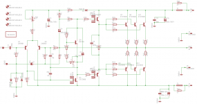
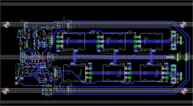
Here you go, the corrected schematic and the in-progress PCB layout, (still lots to do on it yet 😉 ). As these will be running as mono modules, I'm tempted to tighten the layout up a little so I can add the PSU on the end, then it'll be a nice one board solution.
Attachments
Ta, it's getting there. Sitting here, pondering the heatsink, and thinking I might make a sub-assembly PCB with dual rectifiers using MUR840s that will fit on the spare thin section at the top. Eight more holes to tap though... 🙂
Hi Al, have a look at the BYV32E diodes (Hugh put me onto them). If you use both in the package in parallel you will have significantly better current handling, and the reverse recovery time is quite a bit faster than the MUR840's too 🙂
http://www.nxp.com/documents/data_sheet/BYV32E-200.pdf
I'm getting 25 in my next order. (I have a few power-supply's to do 😉 price break at that quantity is 99c each.
Tony.
http://www.nxp.com/documents/data_sheet/BYV32E-200.pdf
I'm getting 25 in my next order. (I have a few power-supply's to do 😉 price break at that quantity is 99c each.
Tony.
Member
Joined 2009
Paid Member
I like the extra output pairs, looking very nice.
wintermute - for my AKSA clone psu I used the singulated diodes BYW29E, same diode as in the dual version for anyone who finds these easier to obtain.
wintermute - for my AKSA clone psu I used the singulated diodes BYW29E, same diode as in the dual version for anyone who finds these easier to obtain.
Chaps, I have tons of 840s, and need to get rid of them somehow. 🙂 This amp is destined to be driving a 15" up to about 250Hz, so I'll probably save the really expensive bits for the mid-high amp/s
no problem Al, If you have em use em! Interestingly the price of the 840's from RS is 30% higher than the byv's.
Thanks Bigun, I'd wondered if there was a singular version. looks like it has slightly lower current capability (8A compared to 2 X 10A) but otherwise the same.
Tony.
Thanks Bigun, I'd wondered if there was a singular version. looks like it has slightly lower current capability (8A compared to 2 X 10A) but otherwise the same.
Tony.
Al,
Very nice layout, compact, even novel in the way you've mounted the outputs in two lines.
But I'm a bit worried about thermal loading. If each device must potentially be able to dissipate up to 40W (rock concert, grinding bass guitar with drum backup) we are looking at 240W dissipated in a small area not much more than 150mm x 60mm. It all depends on whether you use convection or fan cooling. With fins parallel to the two lines of outputs, fan cooling would be fine (though the first transistors always run cooler than the last in line in the airstream), and a narrow heatsink could easily remove the heat. This is the usual solution in compact, 2U pro-audio amps, of course. If convection, then I have my doubts. To remove 240W with less than 30 degree rise over ambient requires 0.125C/W, that's a substantial heatsink at least 300mm long and perhaps 150mm wide, and you should have vertical fins, with one triple line under the other, placed symmetrically around the thermal center of the sink.
Could you talk about the heatsink a bit, to be sure this amp doesn't overheat with high output over a long period? Bear in mind temperatures reach 45C in my city, so I take a worst case scenario of cooling, I might be worrying unduly, but this is a big amp and driven hard the heat output will be considerable. It may be useful to locate the outputs well apart.
Hugh
Last edited:
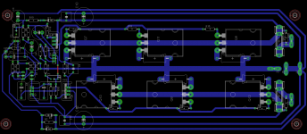
Well, I'd like to say "Great minds..." etc. but as mine is decidedly inferior I'll just say I've been working on compacting the front end so I could spread out the OPs for exactly the same reason.
The plan is to have the heatsinks mounted vertically, and normally convection cooled, but with fan assist triggered from a 70C thermal switch. Most of the time in use they will be running nowhere near full wack, so passive cooling should be fine.
Oh, and if it ever gets to 45C here, I'll be dead, (strawberry blonde! 😉 ).
Attachments
Al,
If you have vertical fins, with the long dimension of the sink vertical also, then two vertical lines of three transistors should work well and you might be able to put your compacted front end and drive sections in between the lines.
The problem with big amps is always the thermal considerations. They dominate the layout. The other issue is that you can configure the pcb on top of the outputs if you wish, with the Vbe multiplier attached to one of the outputs under the pcb and two 0.8mm washers separating the pcb from the outputs on all the others. This also obviates using flying leads for the Vbe multiplier, which can be a PITA to fabricate.
If you had dedicated 15 years of your life to designing a better mousetrap I'm not sure I'd be describing you as a 'superior mind'. Lunatic, more like it......
Hugh
You've actually got me thinking now, I may split the front end board off completely and make it as a separate PCB, and mount it above the output board. Then I could spread the OPs over the whole length of the heatsink...
Member
Joined 2009
Paid Member
I think it could be more hassle with two boards - twice as many to mount and you'll need to connect them with wiring - and which board has the Vbe multiplier on it... Maybe you can design it as a longer board so that the front end could be 'cut off' and separated if needed but if you don't need to separate it off the whole pcb can still operated as a single pcb ?
Hugh - agree with the flying leads part, it's easier when it's all wired into the pcb. The way I took advantage of it in the end was to silicone the Vbe multiplier on top of the package of an output device for really good thermal feedback but that's only cus I didn't have the power devices under the pcb as you suggested.
Hugh - agree with the flying leads part, it's easier when it's all wired into the pcb. The way I took advantage of it in the end was to silicone the Vbe multiplier on top of the package of an output device for really good thermal feedback but that's only cus I didn't have the power devices under the pcb as you suggested.
Last edited:
- Home
- Amplifiers
- Solid State
- Based on Hugh Dean's AKSA 55