ZM - Can you elaborate?
my lips are sealed

it seems , at least to me , in all Papa's projects - always is one detail (or spot ) in schematic which is sort of new or special or just different from common praxis in building electronic gadgets ......
even worse - sometimes he have wicked sense of humor - fact for M2 , written on 6moons site , by Papa :
The bias circuits take a couple of minutes to fully charge but then they settle into high precision. The slow charge is how I avoid that precision from creating any sonic artifacts. The first ones I made took a full 2 minutes before any sound came out at all. You can imagine the messages I got. I should have put something in the manual about it. Something like that's the tubes warming up! Also, as the M2 biases up, the output stage goes from class B to class AB to class A. What you get to listen to is the character of each without feedback. Ontogeny recapitulates philogeny.
based on what I know about that circuit ( I'm not saying that I know everything ) , that's half true , half witty .
so - speaking shortly - biasing of J2 is where humor resides , besides elegance ; genius is used for laying several small puzzles in one greater than sum of puzzles
 your question was rhetorical , so you are given with adequate answer ....
It seems the V sources main job is to make sure the signal the two fets are seeing is balanced. Setting this value properly may be the key.
The Tube CAD Journal,SRPP Optimal Rak Value 3
This is just a guess.
It seems odd that Broskie gave the best description of the SRPP, but seems to not think about using a pentode up top.
The Tube CAD Journal,SRPP Optimal Rak Value 3
This is just a guess.
It seems odd that Broskie gave the best description of the SRPP, but seems to not think about using a pentode up top.
Last edited:
current/voltage contribution between two "halves" of Aleph/SRPP/Mu output stage is matter of constructor's choice ......... or simply tweaking it to smallest amount of distortion vs. planned load
when you're going to pentode on top of triode , result is having more of ideal CCS as load ;
that's path away from having both halves behaving as equally contributing in voltage/current domain , for what you need both elements with finite internal impedance
when you're going to pentode on top of triode , result is having more of ideal CCS as load ;
that's path away from having both halves behaving as equally contributing in voltage/current domain , for what you need both elements with finite internal impedance
Last edited:
my lips are sealed
it seems , at least to me , in all Papa's projects - always is one detail (or spot ) in schematic which is sort of new or special or just different from common praxis in building electronic gadgets ......
even worse - sometimes he have wicked sense of humor - fact for M2 , written on 6moons site , by Papa :
based on what I know about that circuit ( I'm not saying that I know everything ) , that's half true , half witty .
so - speaking shortly - biasing of J2 is where humor resides , besides elegance ; genius is used for laying several small puzzles in one greater than sum of puzzles
I wasn't rhetorical. If you're worried about NP, maybe you can explain how Broskie's article relates to NP's work in general.
current/voltage contribution between two "halves" of Aleph/SRPP/Mu output stage is matter of constructor's choice ......... or simply tweaking it to smallest amount of distortion vs. planned load
when you're going to pentode on top of triode , result is having more of ideal CCS as load ;
that's path away from having both halves behaving as equally contributing in voltage/current domain , for what you need both elements with finite internal impedance
So for PP you need two triodes with clever Vsouce, and pentode up top gives you a nice SE design and moves away from PP.
Magic is manipulating the internal resistance?
.......
Magic is manipulating the internal resistance?
internal resistance - xconductance - gain , whatever .....
it all depends for what you are looking ;
maybe gain is most comprehensive term
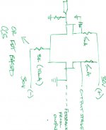
Consider the two power resistors going from the Source of the CS to the
Drain of the primary gain device. The voltage across these resistors and
their added resistance sets the DC bias of the current source. Where you
tap between them sets the gain. You could easily imagine a string of 0.1
ohm resistors, 10 in series forming 1 ohm but the output to the load is
tapped arbitrarily. Then you can adjust to your heart's content either for
low distortion or a particular ratio of 2nd to 3rd harmonic.
The J2 has more gain and runs hotter (higher bias?). As I've noticed in preamps, higher gain and higher bias often correlate with greater weightiness and sweetness.
I found this before seeing the post above.
Also there is info in F3 Help thread about affect of increased bias and voltage and transconductance and how this affects capacitance.
Thank you Nelson. I do not have the fets for the J2, but hope to explore the topology for a higher power SE amp. I want to play with both mu and cascode setup from F3 perhaps combining the two. Hope to get Fets for J2 after exploration of this amp. Interesting how Broskie moves through the possibilities of the mu follower being possibly PP or SE.
Limited understanding of F3 cascode benfits include, protection for sensitive device, no Miller effect, increased control of primary transistor (LU Jfet), modulation per Papa's discovery. This schematic provides most of that with exception of protection and control. Possible added benefit is non inverted output which could be taken advantage of in feedback. Protecton is not needed if SS parts used
Consider the two power resistors going from the Source of the CS to the
Drain of the primary gain device. The voltage across these resistors and
their added resistance sets the DC bias of the current source. Where you
tap between them sets the gain. You could easily imagine a string of 0.1
ohm resistors, 10 in series forming 1 ohm but the output to the load is
tapped arbitrarily. Then you can adjust to your heart's content either for
low distortion or a particular ratio of 2nd to 3rd harmonic.
This sounds like a simple but very versatile idea, although I am not sure what schematic it might be referencing.
Maybe a good way to go on any current source resistor or source resistor.
This sounds like a simple but very versatile idea, although I am not sure what schematic it might be referencing.
Maybe a good way to go on any current source resistor or source resistor.
SRPP. It would be really interesting if there was someway to have a control mechanism that allowed it to be switched from SE w/CS to SRPP P/P. Tube Cad is the best place to read up on it all. If i can get away from the 4 kids, i am eventually goin to try it. Need to get Juli@ card and PC based distrtion software. Nelson has already given us a great deal to work with.
Consider the two power resistors going from the Source of the CS to the
Drain of the primary gain device. The voltage across these resistors and
their added resistance sets the DC bias of the current source. Where you
tap between them sets the gain. You could easily imagine a string of 0.1
ohm resistors, 10 in series forming 1 ohm but the output to the load is
tapped arbitrarily. Then you can adjust to your heart's content either for
low distortion or a particular ratio of 2nd to 3rd harmonic.
I find this description very interesting.
I'm up with a J2 clone. I'm still not happy with the bias and the 6 legged creature. I just don't have enough experience to fiddle with it. I've already blown a FET trying to play - an expensive mistake.
Is there a place to connect the six legged bug with the CCS? I'd welcome reading or a lesson.
Can an input trafo be used in place of a differential pair in a susy application? There is no current sharing at the input of the trafo, so how would the error signal be passed or shared? Would it be possible to use a feedback network to bring opposing signal back to input of transformer and would this work in the same way as the susy concept.
What 6 legged creature are you using?
I ended up with a CNY17-4. I tried a few others, they did not get me where I wanted to go. I have not measured the direct quiescent current, the last time I tired, I blew an output - an expensive mistake. I measured the resistors to the CCS and found the current to the gate of the CCS. I'd like to directly measure the current if anyone can suggest a method that will preserve my outputs.
NYCOne,
How about PM ing me a schematic. I know it is not working, but i would know what you are looking at instead of theorizing. Setting up an PP SRPP or SE Mu follower is easier with depletion mode fets for me because of all the tube circuits out there for help. Using enhancement mode stuff adds certain complexities in the bias area. I have realized this in tryin to come up with schematic with 085 on bottom, with 240 on top. Nelson does call the J2 a Mu follower, and from what little i have read, this is more towards the SE side of things. THis could be all semantics and unimportant, just a thought. He said of his graph earlier, that the r085 did not show any similar device synergy and that using a 240 was feasible, perhaps it is different for the R100's you have.
How about PM ing me a schematic. I know it is not working, but i would know what you are looking at instead of theorizing. Setting up an PP SRPP or SE Mu follower is easier with depletion mode fets for me because of all the tube circuits out there for help. Using enhancement mode stuff adds certain complexities in the bias area. I have realized this in tryin to come up with schematic with 085 on bottom, with 240 on top. Nelson does call the J2 a Mu follower, and from what little i have read, this is more towards the SE side of things. THis could be all semantics and unimportant, just a thought. He said of his graph earlier, that the r085 did not show any similar device synergy and that using a 240 was feasible, perhaps it is different for the R100's you have.
- Status
- This old topic is closed. If you want to reopen this topic, contact a moderator using the "Report Post" button.
- Home
- Amplifiers
- Pass Labs
- SS 120R085 Depletion Mode Jfet