Could a DC Servo like this work, because i don`t would like to throw an IC in this AMP.

Last edited:
I'm still not sure we need a servo yet - if you don't mind a little drift. I'm going to buy a multimeter today that has datalogging capability so I can measure the DC offset every second for an hour and see how it changes. It will be interesting to see the graphs when it's done.
After inserting a phaseledcompensation Cap, i got the filing that the sound is a bit Clearer and less smeary.
Probably due to decrease of Oscillation.
Probably due to decrease of Oscillation.
Yes quite possibly. I found that the oscillation didn't help the sound quality at all.
I bought a multimeter yesterday with logging capability but can not get it to work with my computer as it uses an old school rs232 serial cable and software made for win98. Bought a USB to serial adapter but no good. Taking it back today to swap it for s USB one - if they have any.
I think I'd almost rather go back to a ltp input if it proves too difficult to get it stable without a servo. I'm interested to hear what people think about your jfet servo idea though.
dc offset
check here for a very simple - but somewhat fiddly solution to dc offset for JLH simple class A derivative that may work well on this similar i/p
The Class-A Amplifier Site - JLH Class-A Update
Look for DC offset title
Tim Andrew posted an exact set up method somewhere not sure where.
http://www.diyaudio.com/forums/members/tima.html
perhaps he knows
hope this helps
mike
Last edited:
OK den something like this should do the trick.🙂
Or much easier with single supply and output Cap.

Or much easier with single supply and output Cap.
Last edited:
Thanks Mikelm, I contacted him to ask. Hopefully he will get back to me.
Danspy - looks interesting. Where did you find the information? Does it need a resistor to limit the LED current?
Danspy - looks interesting. Where did you find the information? Does it need a resistor to limit the LED current?
Well, from my side, when I finally can get around to building this amp, I will not sacrifice either the single i/p transistor or the the DC coupling - so my drift issues will be considerably more that you are dealing with now but this may be helped by the fact that I am aiming for a fully balanced working system so hopefully my two amps will drift together.
But Tim Andrews has demonstrated that reasonable drift & DC linking are possible and in my experience there are great sonic advantages across the whole frequency spectrum from avoiding any kind of caps ( or transformers ) in the signal path and I tried some fairly expensive film types but confess to not try Teflon caps yet - the extreme cost put be off !
But Tim Andrews has demonstrated that reasonable drift & DC linking are possible and in my experience there are great sonic advantages across the whole frequency spectrum from avoiding any kind of caps ( or transformers ) in the signal path and I tried some fairly expensive film types but confess to not try Teflon caps yet - the extreme cost put be off !
Well, from my side, when I finally can get around to building this amp, I will not sacrifice either the single i/p transistor or the the DC coupling
I'm hoping to keep it as is as well. Looking forward to Tim's reply as I have been unable to find his schematic yet (while spending limited time looking at work 🙂)
This is my final Schematic, after changing the Gate Resistor,s to 560Ohm and adding a 330p Cap to the N channel, the sound is just astonishing specially the bass is much deeper and more contoured.
I never hired something like this before.
I never hired something like this before.

Last edited:
You have built a very special, your own, variant of the amplifier.
I am happy you like your sound. And happy you like my idea.
Good work, danspy 🙂
I am happy you like your sound. And happy you like my idea.
Good work, danspy 🙂
DC Offset
All,
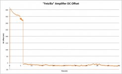
Here are the DC offset results. Test interval is 0.5 seconds for about 50 minutes into a 7 ohm resistor. As you can see it did stabilise at about -20mV at about 7min or so...but I wonder what the hell happened to make it drop from +325mV or so!? I will have to test again and confirm if this happens every time.
So what are your thoughts regarding the need for a servo or other offset control? I think I could now readjust and have it stabilise at +/- 10mV, but the high offset on power up is a worry.
Cheers,
Greg.
All,
Here are the DC offset results. Test interval is 0.5 seconds for about 50 minutes into a 7 ohm resistor. As you can see it did stabilise at about -20mV at about 7min or so...but I wonder what the hell happened to make it drop from +325mV or so!? I will have to test again and confirm if this happens every time.
So what are your thoughts regarding the need for a servo or other offset control? I think I could now readjust and have it stabilise at +/- 10mV, but the high offset on power up is a worry.
Cheers,
Greg.
Attachments
Last edited:
Hmm, interestingly the big drop at 7min can be induced instantly by touching the input. It would seem that when the amp is first turned on with no source attached it is in some kind of metastable state, and just the slightest stimulus can make it stabilise. Probably even the noise from a source would be enough....
Maybe no servo is needed?
Maybe no servo is needed?
Last edited:
I think this is an acceptable value Greg. Even if you have implemented a servo, you will keep seeing the amplifier out drifting to the negative side, then the servo taking it back to 0 and so on.
okay... uhmm I was about to comment on the design on the first page when i realized that the thread has 32 pages! And the last schematic does not look like the first one at all.
Am i missing something?
What i wanted to say. Many years ago i build an amp looking close to the first one. Except that i used mosfet in the inputstage too.
The ZVP3310 capacitance changes a lot accross the VDS range.
The sound was not that good in my opinion compared to my CFB designs. (yes there are several designs).
A bit to dark side. Details was there but it was not neutral at all.
Hi Sonnya,
Can we see one or more of your designs that you preferred to this type of design ?
The original design evolved by general agreement through this thread with some individual variations.
Can we see one or more of your designs that you preferred to this type of design ?
The original design evolved by general agreement through this thread with some individual variations.
No problem.
I am trying to locate them right now.
First two of them. They are CFP amp both of them.
The 2037a2.pdf
We have listened to the 2037a2 but it will suddenly oscillate. It is the CFP output stage.
But it is very vivid amplifier to listen to.
http://sitosite.dk/amps/mirand-a1a.pdf
The Mirand A1 V1.1 is very neutral and goes very deep. One of the guys from denmark has it running instead of an Advantage integrated amp (I think it is an i200?!). It outperforms the amp on the level of detail and ability to deliver power when needed.
The bias current is only 100mA, and it does not change the sound a lot in the warmup phase.
Attachments
Last edited:
- Status
- Not open for further replies.
- Home
- Amplifiers
- Solid State
- JFET input, MOSFET VAS, LATERAL output = Perfect!!