I gave it a quick try with the suck-out capacitor, but i like it more without it.
It sounds more like Bipolar output den Mosfet, specially the bass got tinned out more Kick but less Grunt.
It sounds more like Bipolar output den Mosfet, specially the bass got tinned out more Kick but less Grunt.
Metal,
Here are the figures. It would seem that the sucker cap helps at 2kHz and is detrimental at 20kHz. Note these figures are at about 22v p-p output. Seems it would be worth using one in that case as I can't even hear 20kHz. Maybe there's a measurable reason for why l prefer the sound with it in after all.
2kHz with sucker cap:
Fourier components of V(to_spkr)
DC component:0.0138852
Harmonic Frequency Fourier Normalized Phase Normalized
Number [Hz] Component Component [degree] Phase [deg]
1 2.000e+03 1.077e+01 1.000e+00 0.26° 0.00°
2 4.000e+03 1.171e-03 1.087e-04 -99.77° -100.02°
3 6.000e+03 1.723e-03 1.599e-04 3.53° 3.28°
4 8.000e+03 5.715e-04 5.306e-05 86.34° 86.09°
5 1.000e+04 4.196e-04 3.896e-05 -178.06° -178.32°
6 1.200e+04 2.265e-04 2.103e-05 -90.46° -90.71°
7 1.400e+04 1.429e-04 1.327e-05 -0.68° -0.94°
8 1.600e+04 7.802e-05 7.244e-06 86.67° 86.41°
9 1.800e+04 3.862e-05 3.586e-06 178.45° 178.19°
Total Harmonic Distortion: 0.020595%
2kHz without sucker cap:
Fourier components of V(to_spkr)
DC component:0.0145908
Harmonic Frequency Fourier Normalized Phase Normalized
Number [Hz] Component Component [degree] Phase [deg]
1 2.000e+03 1.077e+01 1.000e+00 0.27° 0.00°
2 4.000e+03 2.753e-03 2.555e-04 -87.40° -87.66°
3 6.000e+03 2.442e-03 2.267e-04 5.93° 5.67°
4 8.000e+03 1.128e-03 1.047e-04 97.18° 96.92°
5 1.000e+04 6.313e-04 5.859e-05 -169.94° -170.21°
6 1.200e+04 2.522e-04 2.341e-05 -77.84° -78.11°
7 1.400e+04 3.497e-05 3.246e-06 10.23° 9.97°
8 1.600e+04 8.356e-05 7.756e-06 -72.68° -72.95°
9 1.800e+04 1.246e-04 1.156e-05 17.52° 17.25°
Total Harmonic Distortion: 0.036304%
20kHz with sucker cap:
Fourier components of V(to_spkr)
DC component:0.0132126
Harmonic Frequency Fourier Normalized Phase Normalized
Number [Hz] Component Component [degree] Phase [deg]
1 2.000e+04 1.071e+01 1.000e+00 -0.10° 0.00°
2 4.000e+04 1.061e-03 9.904e-05 -105.91° -105.81°
3 6.000e+04 2.070e-03 1.932e-04 46.34° 46.45°
4 8.000e+04 5.842e-04 5.452e-05 143.10° 143.20°
5 1.000e+05 5.539e-04 5.170e-05 -112.98° -112.88°
6 1.200e+05 3.031e-04 2.829e-05 -22.04° -21.93°
7 1.400e+05 1.686e-04 1.574e-05 73.58° 73.68°
8 1.600e+05 8.860e-05 8.269e-06 -170.81° -170.71°
9 1.800e+05 7.558e-05 7.054e-06 -79.16° -79.06°
Total Harmonic Distortion: 0.023223%
20kHz without sucker cap:
Fourier components of V(to_spkr)
DC component:0.0127333
Harmonic Frequency Fourier Normalized Phase Normalized
Number [Hz] Component Component [degree] Phase [deg]
1 2.000e+04 1.072e+01 1.000e+00 -0.09° 0.00°
2 4.000e+04 3.822e-04 3.565e-05 -0.16° -0.06°
3 6.000e+04 1.582e-03 1.475e-04 78.07° 78.17°
4 8.000e+04 3.238e-04 3.020e-05 -170.82° -170.73°
5 1.000e+05 2.356e-04 2.197e-05 150.60° 150.69°
6 1.200e+05 5.721e-04 5.335e-05 -145.37° -145.28°
7 1.400e+05 5.804e-04 5.413e-05 -64.54° -64.45°
8 1.600e+05 3.747e-04 3.495e-05 -9.06° -8.97°
9 1.800e+05 5.225e-04 4.874e-05 7.96° 8.05°
Total Harmonic Distortion: 0.018387%
Dear swordfishy,
could I possibly suggest You look at the gain structure through Your circuit?
That should potentially give a good indication of why You seem to have 3rd harmonic as dominant at 20kHz? I know it's out of most of Our hearing ranges, but it does affect the perceived transient performance in the upper registers...
Your chosen classic (American?) VAS resistor loading, might not be particularly good, with a very highly impedant and voltage controlled Vert. MosFet?
It is normally used in current controlled BiPolar designs, to my humble knowledge.
The resistors will load the VAS very hard and this could result in increased distortion especially at higher frequency's, where the capacitances of the Output MosFet's, is also coming in to play, with their loading.
Otherwise the remedy could be more current and therefore a higher power VAS Fet...
I would though personally recommend to shy away from IR's and the small TO-220 Hitachi's for this purpose - I tried them for this application and did not like the produced sound much...
To 'Screechy' comes to my admittedly (lycky in this case) fading mind...
I think there to be something in odd packages though - TO-92L, TO-251, SMD and what have U - Toshiba has one in TO-220F that might work, but I have not tried it and am therefore not able to comment on suitability? Seen them available on eBay though. They should have a reasonable low threshold Vgs Voltage as well?
Be aware of not to high input capacitance though - that will adversely load Your 1st stage at high frequency's as well, so You potentially forward the problem here...
Other remedy could be to re-invoke a current generator here, instead of the resistor network?
Could of course change VAS for BiPolar, but that would somehow defy the object of an all Fet amp signal path somewhat - oder?
Hope this is of the intended good help intended with best regards
DocO😎
Hi swordfishy,
good news - I can't wait to build mine.
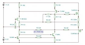
this is the best I came up with so far using a .22 ohm o/p res but in my experience bought o/p resistors often sound dreadful therefore my 0.22 ohm resistor would be a small length of "constantan" resistance wire which would double as an o/p fuse which I will need because mine will be DC linked - the 5nF after the 0.22 res in an essential part of the design.
if all that sounds too complicated probably a 1uH choke with 1ohm in parallel will also work - but I did not try that with this exact arrangement
you can see I did my compensation from the VAS - this was the best arrangement I tried - at least in spice - this was a JLH technique.
adding any miller cap made things worse
the BJT hawksford cascode helped with stability
but if your's sound great already then perhaps just enjoy it 🙂
mike
Hi mike,
I appreciate You can't currently build the proposed, but is there any chance You could upload the distortion spectrum's from this simulation, like swordfish 2k & 20kHz?
Would be nice to see the difference out of sheer curiosity😎
Best regards
DocO
Hi swordfishy,
good news - I can't wait to build mine.
this is the best I came up with so far using a .22 ohm o/p res but in my experience bought o/p resistors often sound dreadful therefore my 0.22 ohm resistor would be a small length of "constantan" resistance wire which would double as an o/p fuse which I will need because mine will be DC linked - the 5nF after the 0.22 res in an essential part of the design.
if all that sounds too complicated probably a 1uH choke with 1ohm in parallel will also work - but I did not try that with this exact arrangement
you can see I did my compensation from the VAS - this was the best arrangement I tried - at least in spice - this was a JLH technique.
adding any miller cap made things worse
the BJT hawksford cascode helped with stability
but if your's sound great already then perhaps just enjoy it 🙂
mike
Hi mike and swordfishy as well,
have You guy's tried capping the 1st stage source resistor and/or the VAS degenerating one, for HF compensation and stability?
Much better there, if You can make it stable, than a large 'miller cap' on the VAS or directly in the FB - those will severely limit the OLBW and thereby the available FB gain for HF distortion reduction, to my knowledge and loads of test's...
I'm also 'seconding' Miib's point re. lateral source resistors, by the by - could be maybe just 'a Danish thing' though?
Best
DocO
Last edited:
DocO,
Thanks for your input, it's most appreciated and you have raised some valid points.
You are probably right about the VAS. It may indeed be worth going back to a CCS for this stage. In fact, that was the original plan but we dropped it for the extra simplicity of the bootstrap VAS. I will try to solder up a revised board with a CCS VAS over the coming week, though I am rapidly running out of parts and my perf board looks like a jungle.
As for the degen bypassing....good idea, will try it.
I decided last night that I wanted enough gain to make the amp clip with the input from an ipod (not that I would ever use one as my primary listening source). So I upped the feedback resistor to 1k again....oscillations were back. Tried bypassing the feedback resistor with up to 330pf of capacitance. No good. This thing just loves to oscillate. Anyway, what I am trying to say is that any suggestions you have for improving stability are most appreciated and I will try them all.
Source resistors will come out once the final design is settled on. In the meantime they are a convenient way of measuring Iq.
Thanks again,
Greg.
Hi Greg,
with very fast amps, that are effectively radio transmitters ( and receivers ), the layout is a crucial part of creating a stable design ( and low distortion )
Please excuse me if you already having done this - but you have to have unscreened inputs & and outputs not too close or running parallel and ideally running at 90 degrees to each other.
I usually try to have i/p, PSU & o/p all in different plains.
I think if this is not yet done it is not really the time yet to take further measures because when the layout changes susceptibility to oscillation can change drastically.
mike
Last edited:
DocO,
Thanks for your input, it's most appreciated and you have raised some valid points.
You are probably right about the VAS. It may indeed be worth going back to a CCS for this stage. In fact, that was the original plan but we dropped it for the extra simplicity of the bootstrap VAS. I will try to solder up a revised board with a CCS VAS over the coming week, though I am rapidly running out of parts and my perf board looks like a jungle.
As for the degen bypassing....good idea, will try it.
I decided last night that I wanted enough gain to make the amp clip with the input from an ipod (not that I would ever use one as my primary listening source). So I upped the feedback resistor to 1k again....oscillations were back. Tried bypassing the feedback resistor with up to 330pf of capacitance. No good. This thing just loves to oscillate. Anyway, what I am trying to say is that any suggestions you have for improving stability are most appreciated and I will try them all.
Source resistors will come out once the final design is settled on. In the meantime they are a convenient way of measuring Iq.
Thanks again,
Greg.
Hi Greg,
I have actually had some more thoughts about Ur circuit so far and before U start 'tearing up everything', let me make the following further suggestions pls?
It is possible You could make it work with the current 'American' bootstrapped FB technology and VAS Fet, if You possibly considered replacing (one at a time) or both of the resistors 'at the bottom' of the circuit, with current sources?
The current source will work as an impedance transformer and make life a lot easier for the VAS Fet impedance wise and as added benefit will also hold (of course) the current virtually constant. This will most certainly benefit Ur described stability issues and should also provide better clipping control at the negative part of the slope...
Sure the output Fet would also like this possibly better controlled Voltage swing?
I have also had a look for the 'upgraded' VAS Fet in Toshiba form and it is 2SJ313. They are for sale on eBay and their characteristics from the data sheet do indeed look promising for Ur application.
I looked at these parts myself, but needed higher break down Voltage than -180V, which in Your case will be more than adequate...😎
Please enjoy and many tnx for the nice appreciative words and with
the best regards
DocO
Last edited:
Hi Greg,
I have actually had some more thoughts about Ur circuit so far and before U start 'tearing up everything', let me make the following further suggestions pls?
It is possible You could make it work with the current 'American' bootstrapped FB technology and VAS Fet, if You possibly considered replacing (one at a time) or both of the resistors 'at the bottom' of the circuit, with current sources?
The current source will work as an impedance transformer and make life a lot easier for the VAS Fet impedance wise and as added benefit will also hold (of course) the current virtually constant. This will most certainly benefit Ur described stability issues and should also provide better clipping control at the negative part of the slope...
Sure the output Fet would also like this possibly better controlled Voltage swing?
I have also had a look for the 'upgraded' VAS Fet in Toshiba form and it is 2SJ313. They are for sale on eBay and their characteristics from the data sheet do indeed look promising for Ur application.
I looked at these parts myself, but needed higher break down Voltage than -180V, which in Your case will be more than adequate...😎
Please enjoy and many tnx for the nice appreciative words and with
the best regards
DocO
You can take a look how I make bootstraped+CCS VAS at this thread.
http://www.diyaudio.com/forums/solid-state/186981-bootstrapsccs-t-tmc.html
dado
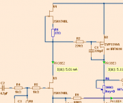
Here is another improvement.
Replace the drain resistor of the 2SK170
with one current source CCS in form of one JFET.
Gives lower distortion.
Note also the increased value of compensation cap: 220pF
It looks as it at least should be 100pF, like danspy uses.
Replace the drain resistor of the 2SK170
with one current source CCS in form of one JFET.
Gives lower distortion.
Note also the increased value of compensation cap: 220pF
It looks as it at least should be 100pF, like danspy uses.
Attachments
Here is another improvement.
I mentioned this one already but Aksa comment that this just increase OLG by order of magnitude - which is going in wrong direction when we consider stability . . .
That is one reason I went exploring in the land of less OLG 😉
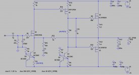
Hi All,
As was suggested earlier, I have gone back to the CCS VAS. Lineup will be laughing to himself as we are now back where we started the thread! Guess you can't improve on a good design. Anyway it is a worthwhile improvement, amazing actually. Here is why.
1) As docO predicted, the amp is more stable. I was not expecting this as I have had issues with oscillating CCSs before. I was able to increase the gain to something more useful with no oscillation problems. Still with no compensation of any kind.
2) The performance. Square wave performance is improved....though it was pretty amazing to begin with. This amp eats a 20kHz square wave for breakfast.
3) The sound. This amp has gone from sounding great to absolutely phenomenal. Some of the warmth is gone, but the detail and clarity has improved substantially. This amp has the potential to ruin me as an audiophile. Can it really get any better than this? It sounds absolutely amazing. Some of the warmth is still there (just a bit), but the separation and transparency is vastly improved. I can now see that the bootstrap was adding quite a bit of coloration.
I prefer the amp this way, but some of you tubeophiles might like it more with the bootstrap VAS.
Have no fear, even with the ccs VAS I guarantee you will be tapping your feet!
That said, the extra stability and extra gain it allows is a big plus!
Anyway, here is the current schematic:
Attachments
Last edited:
Hi,
...and sound quality. Increasing the open-loop gain lowers the distortion according to the simple op-amp concept back-upped by the likewise simple simulators. You can employ active current source and reduce the stage gain with a resistor to ground.which is going in wrong direction when we consider stability . . .
In the schematic I posted in post 292, please note that the amp simulates much better with equal gate resistors for the output fets. Going to go try it in the real circuit now...
If you insert the jfet.. i believe it'll be even better...and a Hawksford cascode to make it a bit more scalable
Nice...😉
Nice...😉
swordfishy,
instead of those ugly nonlinear noisy MOSFETs you should use a JFET in the input and a bipolar in the VAS.
instead of those ugly nonlinear noisy MOSFETs you should use a JFET in the input and a bipolar in the VAS.
Square wave
All,
Here is the 20kHz square wave at 20v P-P, with 500R gate stoppers on both output fets. Could be even better with smaller gate stoppers I guess, but this is plenty fast, and nice and stable too!
Wuyit, I will be replacing the input fet with a 2SK170 as soon as they arrive. I ordered them a week or two back.
Attachments
If you insert the jfet.. i believe it'll be even better...and a Hawksford cascode to make it a bit more scalable
Nice...😉
Thanks miib.
It's on the cards. Beauty is that now that I have it stable i can make pcbs and easily swap for the jfet when they arrive as the pinouts a the same.
Need to do a long term dc offset test....just to make sure I don't need a servo. The dc offset does wonder a bit.
Ok well it seems that 500R gate stoppers are the best compromise between ringing and rise/fall times. The rise and fall time of the old bootstrap ccs was better, but the corners were a lot more rounded. I think given the simulated 10 fold improvement in distortion of the bjt ccs vas it is worth sticking with it, despite the slightly slower performance.
- Status
- Not open for further replies.
- Home
- Amplifiers
- Solid State
- JFET input, MOSFET VAS, LATERAL output = Perfect!!