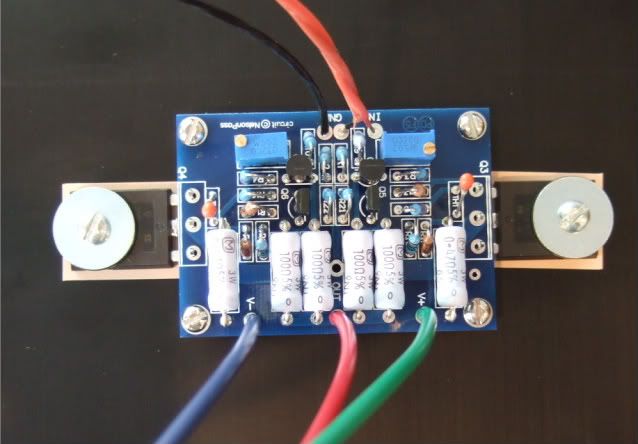
here's my setup so far...
[/IMG]
Edit: on a closer look, I think marra is right... plus to V- is not good.
Last edited:
merlin2069er - Yes, your primaries are connected incorrectly. And the AC. I can't comment to the PCB connections because I'm not familiar with the layout of the board.
Hang on for a little while longer I can draw all of it out for you this evening, but I must take my son to his swimming lesson right now!
You are very close, just a few re-arangements on your terminal strip and you will be there!!
Hang on for a little while longer I can draw all of it out for you this evening, but I must take my son to his swimming lesson right now!
You are very close, just a few re-arangements on your terminal strip and you will be there!!
How much smoke did you see and do you have any idea where it came from.
Btw. I edited my response above. If you mains connection is correct, you could try to swap the + and - on the V- bridge and fire it up again. Do you have a variac?
Btw. I edited my response above. If you mains connection is correct, you could try to swap the + and - on the V- bridge and fire it up again. Do you have a variac?
It was a small quick poof, not that big - I got it because I had the resistors in the wrong spot.
ok, I see where I've made my mistake. I've got the light bulb on power cord.
But, I'll have to pick up additional fuses, I've blown them all. 😱
ok, I see where I've made my mistake. I've got the light bulb on power cord.
But, I'll have to pick up additional fuses, I've blown them all. 😱
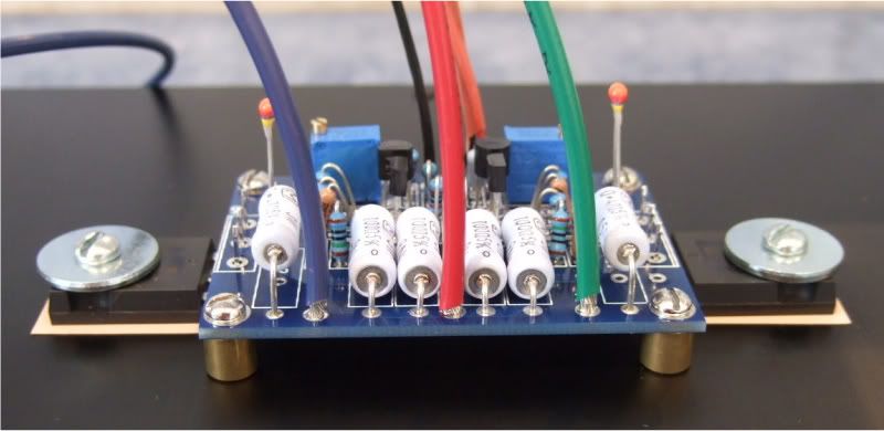
I've colored the wires, it's should be crystal clear.

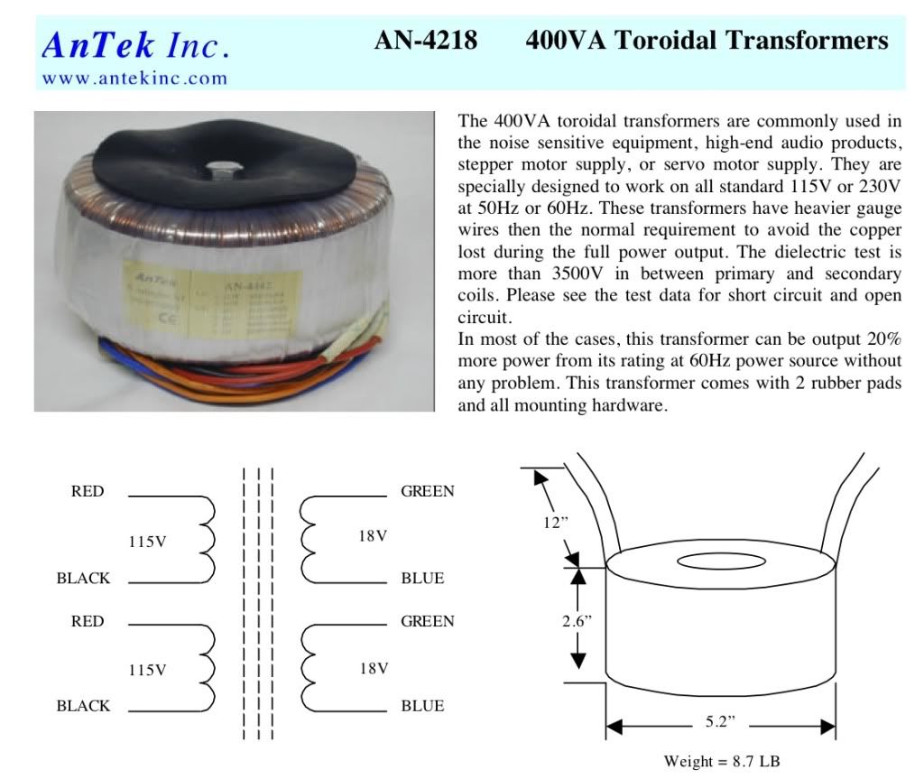
Here is the AnTek datasheet -
Last edited:
Mybe I'm not understanding, but I was going to twist both red primaries together and both black primaries together, to the power input.
You're right, in assuming to parallel the primaries for 120 VAC operation, you connect the two reds together, and the two blacks together (assuming you are using an Antek, true?) HOWEVER, with the in-rush limiters (CL-60s), you should include them as if they were part of the two primary windings. The schematic shows how to do this, but in a "word picture":
1. Pick one of the two primary windings (paired red and black leads).
2. To the winding you pick, attach one led of the CL-60 to the primary's red lead. Now, your new "red lead" is effectively the unused wire of that CL-60.....the lead that is not yet connected.
3. Put that winding aside for now....
4. Now, pick the OTHER primary winding (again, with paired red and black leads).
5. Attach the second CL-60 to that primary winding's black lead (from step 4). Now, your new "black lead" is effectively the unused wire from that CL-60.
(In doing steps 1-5, above, you've added one CL-60 in series with each of the two primary windings, as the schematic requires).
Now you can connect the "red lead" of the one CL-60 to the "red lead" of the other primary's winding. And connect the "black lead" of the other CL-60 to the other primary's winding.
Add the X2 capacitor to the mains input, along with the switch and fuse, and you have your primary wired correctly. Study the schematic that 6L6 has posted. The "word picture" above matches his diagram. Best to use a good "industrial quality" terminal strip to tie together your "mains-side wiring" as required.
Ken
Last edited:
Ok, as promised. Here is the mains to the transformer primary -
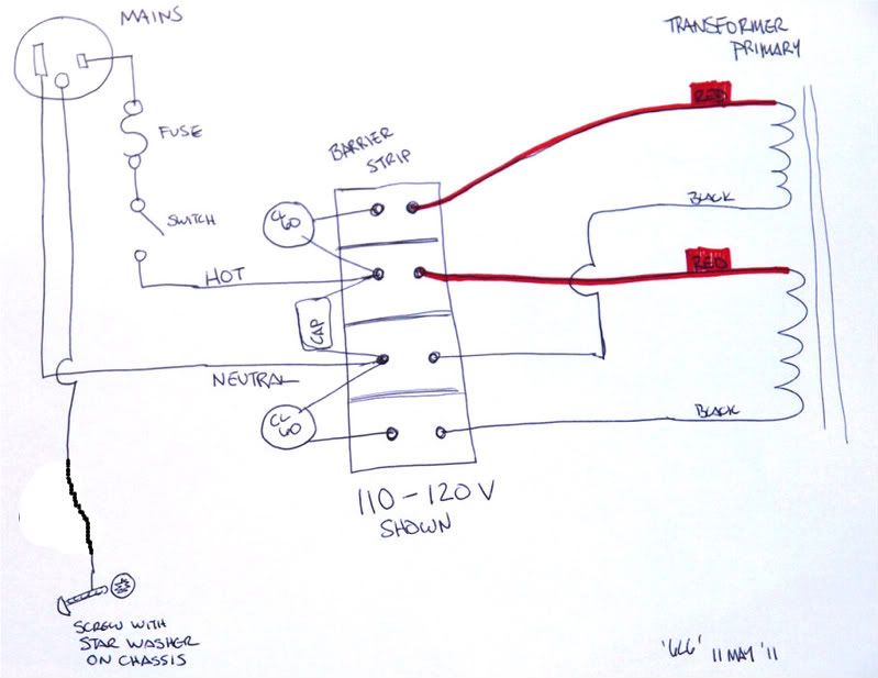
Now that's about as clear as it could be. Even I understand it!
Russellc
F5
Thank you ,
Your pictures help a lots ;I have similar transformer fr Antek 625VA ,hesitated
to fire up ....until i triple check with yours(pic)
GOOD WORK
The original, if you are interested -- http://www.diyaudio.com/forums/pass-labs/182723-how-build-f5.html There are lots of neat questions and answers in that thread.
LOTS OF PHOTOS. IT WILL TAKE TIME TO LOAD THE PAGE.
Nothing out of the ordinary, Peter Daniel boards, single transformer, Tech-DIY transistors and other bits, HiFi2000 chassis.
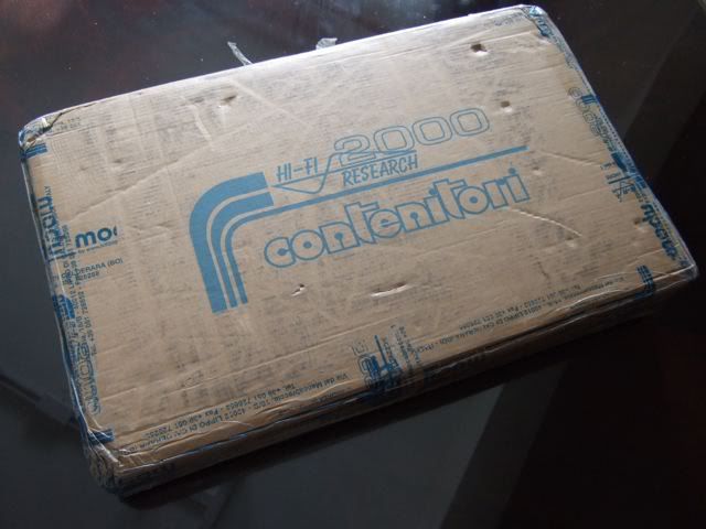
I have collected all the pieces and finally today the chassis arrived from Italy! I am ready to start!
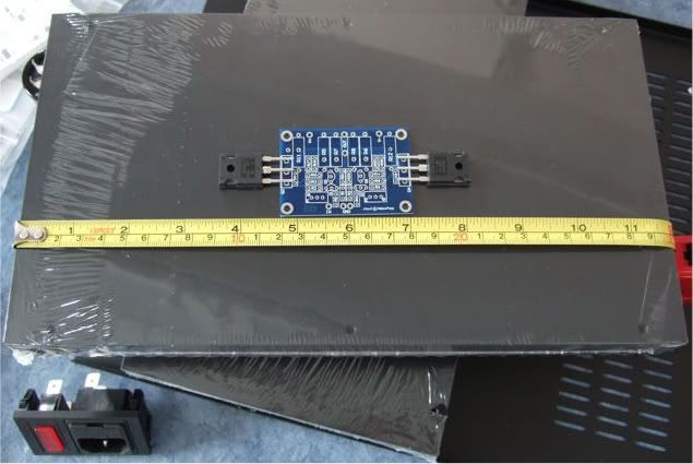
This is From Modushop.biz, it's a "Pesante Dissipante 4U depth 300 mm" (6 1/2" tall x 11 3/4" deep x 19" wide) Which will have a different specific number depending on color and faceplate thickness. I needed to get the shallow(300mm) case, if you have the room for it, you could get the 400mm deep.
Here is the obligatory "armory" photo. Only one of the amp channels shown.
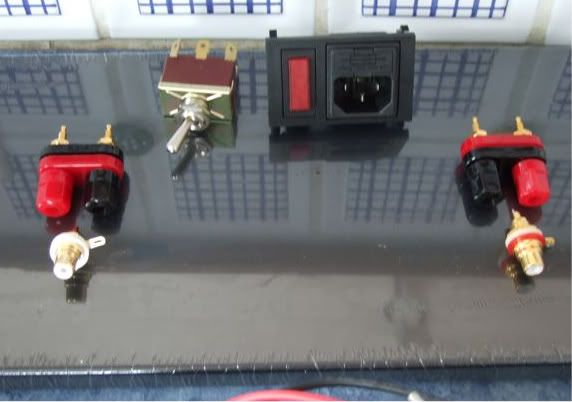
The rear panel. I thought I ordered an Inlet Module with a switch, but I didn't read the datasheet well enough, and it has a neon light power indicator instead. Oh well. Luckily I have a couple of nice bat-handeled switches, I will use one here. The Jacks and RCAs are also from my box, I think they are Vampire.
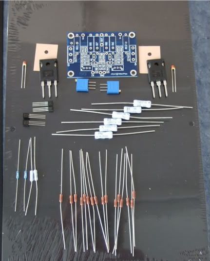
Here are the contents of the Tech-DIY F5 kits, the Peter Daniel's boards, and a couple of silpads.
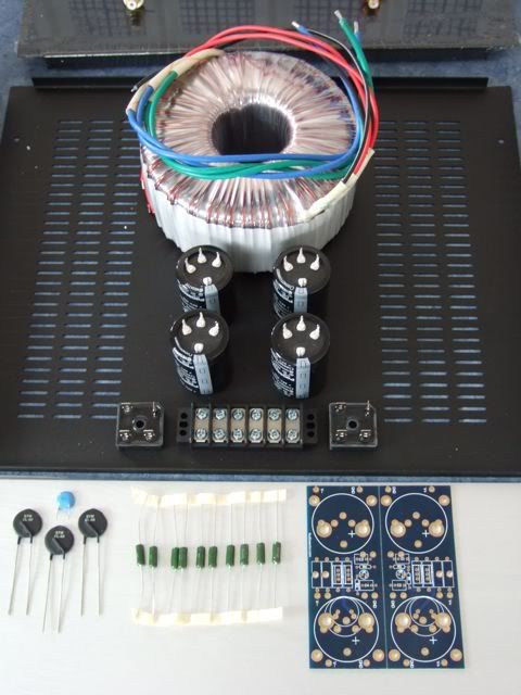
The PSU components. Vishay rectifier blocks, Peter Daniel PSU board, resistors, 33,000uf capacitors, CL-60 thermistors, and a big-honkin' 600VA transformer.
When I was determining the transformer size necessary I must have had a brain-sneeze, I must have only thought of one secondary! Oh well, it was only $20 more than the 'proper' (400VA) size. The 4-pin caps will work on the board with just a bit of modification.
If you were wondering, the Peter Daniel boards are very small. Also very nice!
As mentioned earlier I needed to get a few more things before proceeding with the build…
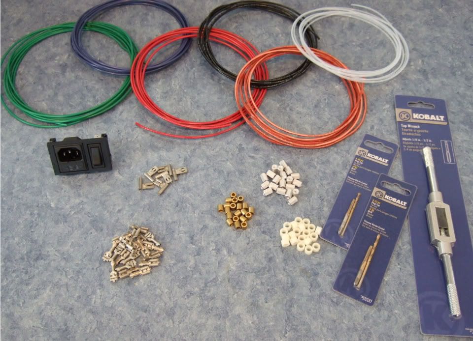
Specifically, wire, connectors, standoffs, spacers, and a tap set. (also a couple of other things not photographed.)
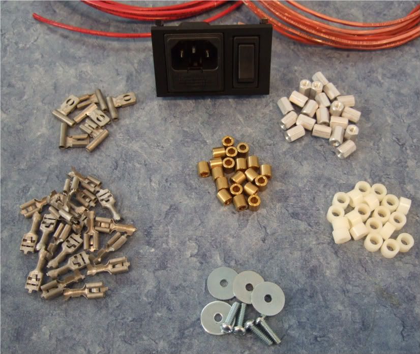
As I am not exactly sure what will be the best standoff/spacer, I bought an assortment. Brass, Nylon, and 'real' 6-32 thread standoffs. Also shown are the 1/4" connector spades, the 6-32 bolts and fender washers for mounting the power transistors.
Also note the Power Inlet module now has a switch!
Not photographed is a big pile of 4-40 hardware for mounting the boards, as well as a few more 6-32 bolts for the rectifier blocks and barrier strip.
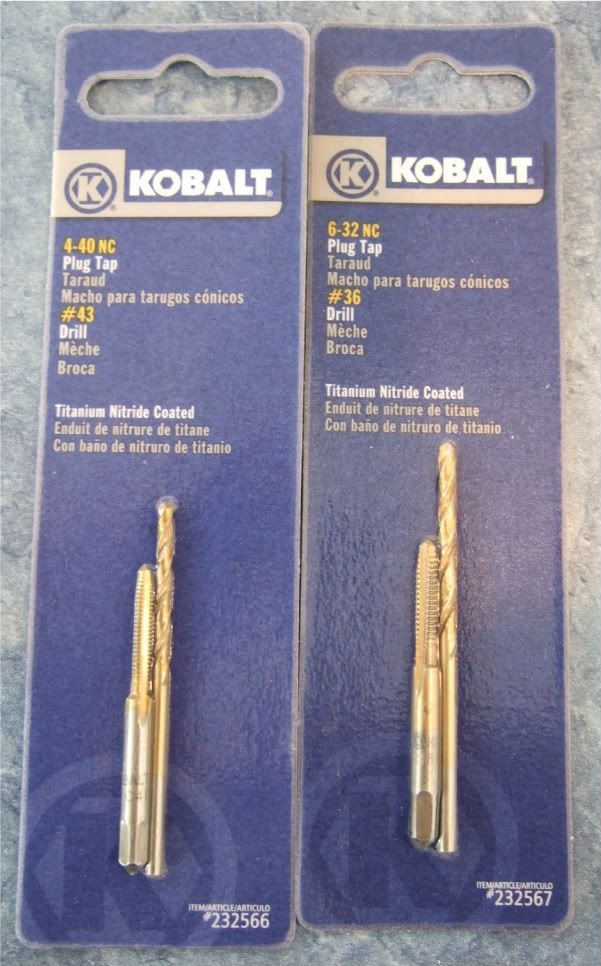
The store I went to didn't have taps without the drill bits, but since they are the exact size for the tap, I didn't see any disadvantage in getting them.
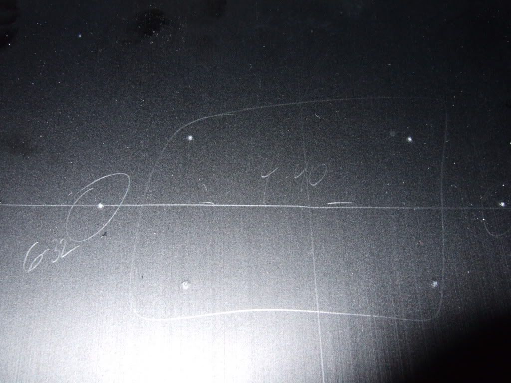
Trying to detemine the best layout for the bottom panel. The Transformer is positioned in the front of the case.
I like this better, it will lead to more symmetrical wiring. Which although not necessary, appeals to me.
If I had the 400mm deep chassis I would also have the power inlet and the barrier strip on the centerline.
I think it is a good idea to leave the chassis vents unobstructed, to keep the heat exchange/airflow as good as possible.
Today I got some drilling done. A lot of effort with not much to look at...
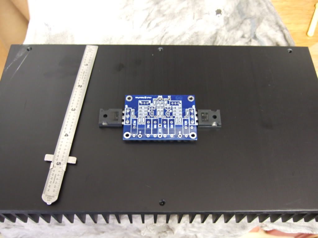
This is the amp board and the 2 power transistors. They will be mounted to the middle of the heatsink.
Once the hole locations are marked, I made some starter holes with a set punch. The 4 in the middle will be 4-40, the two on the outside 6-32
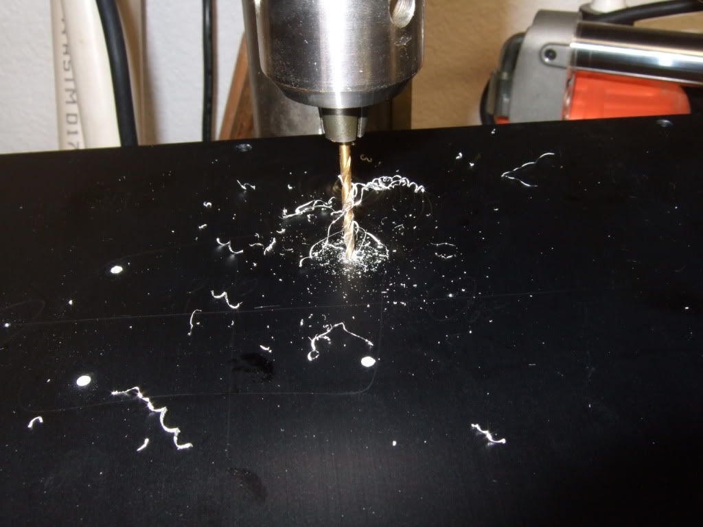
Drilling. Wear safety glasses!
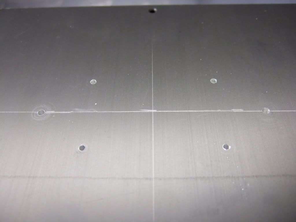
Drilling complete.
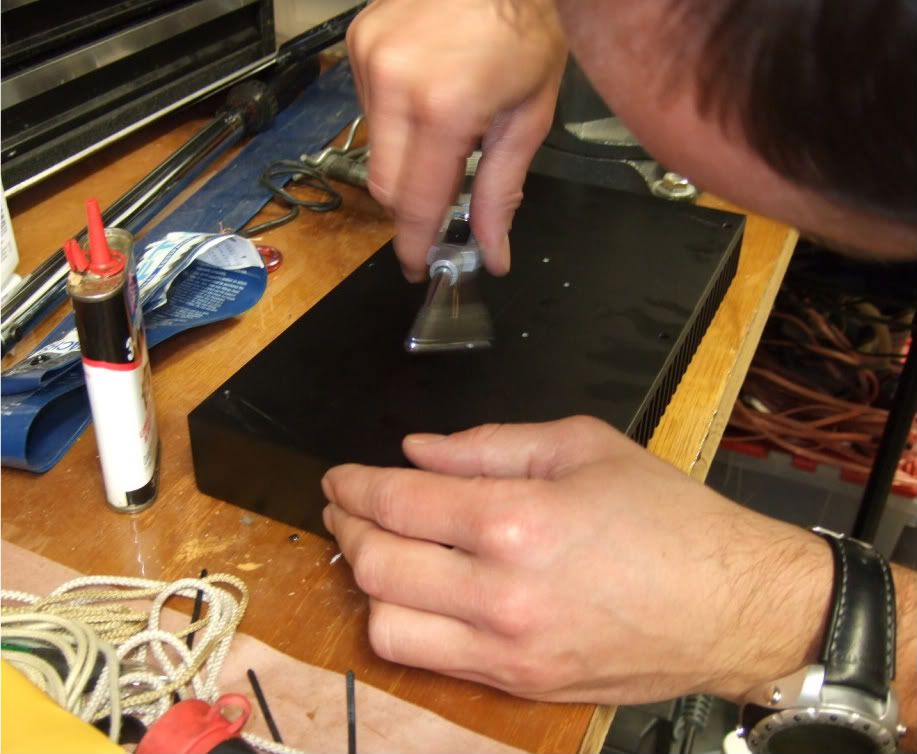
My friend was kind enough to tap the holes.
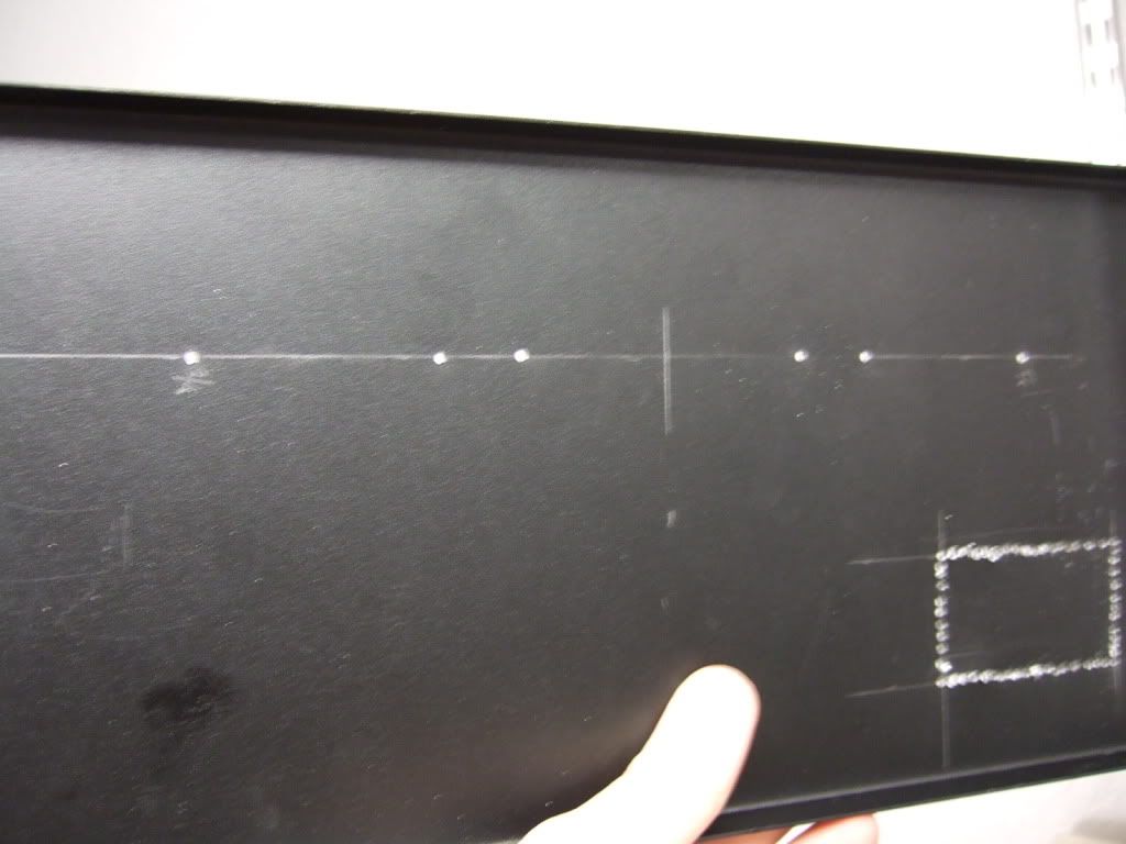
Pilot holes for the RC jacks and Speaker posts. Also the beginning of the IEC inlet module cut-out.
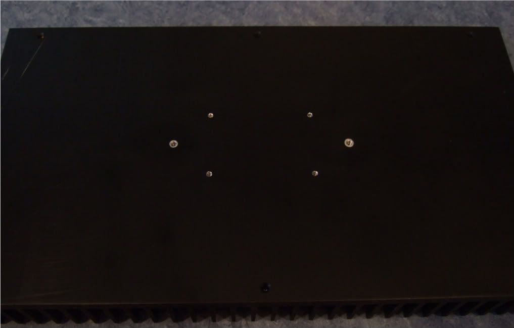
I have all I need in place to build the amplifier circuit and mount it to it's heatsink -
Here is the heatsink, with the holes sanded smooth and cleaned with rubbing alcohol to remove the last oil and sandings/shavings.
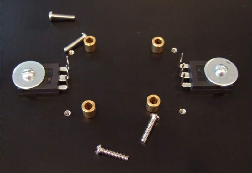
Here is the hardware, 6-32 bolts and fender washers on the transistors, brass spacers and 4-40 bolts on the board
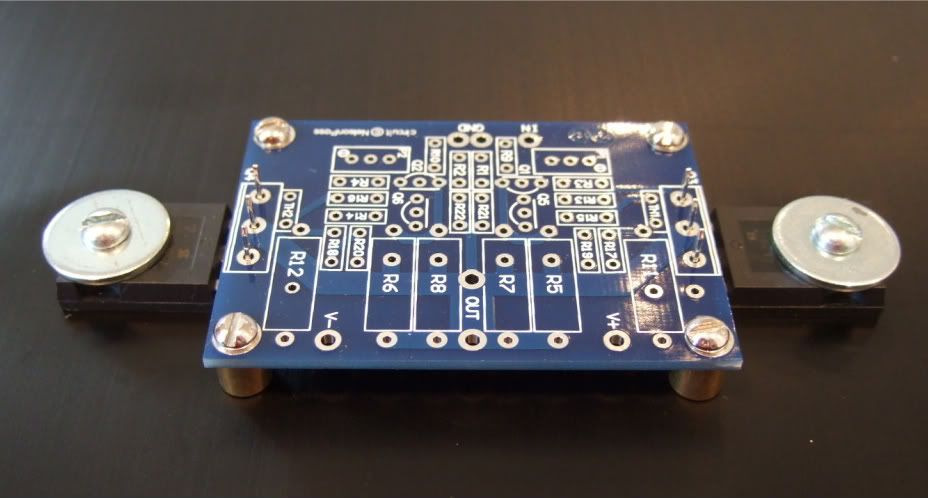
A dry run, to check fit.
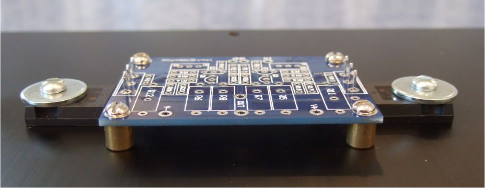
Spacing looks good! Now to complete the board...

Stuffing the board. Have your meter at the ready and measure everything before soldering!!! It will save headaches later!!

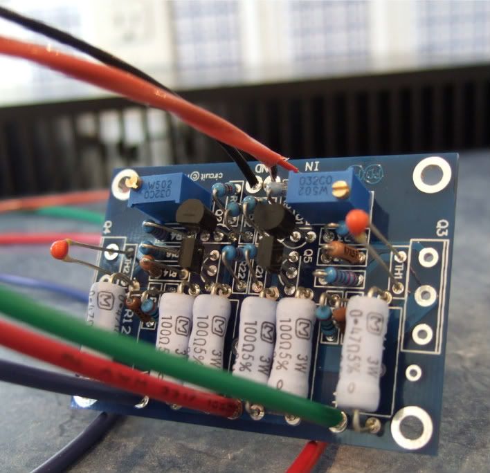
OK, the board is stuffed and the wires attached. My color coding is as follows;
Black - ground
Blue (V-)
Green (V+)
Red (+) out
Red/black twisted pair in orange jacket is input + and -
I like to have the wires much longer than needed to help facilitate neat and tidy wiring later.
On the heatsink with silpads attached.
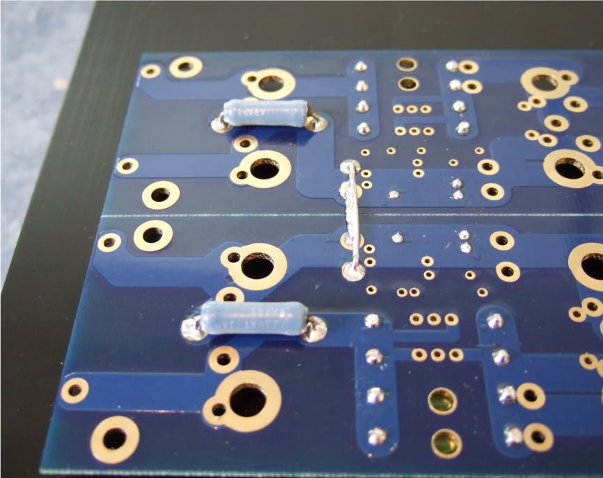
In this photo you can see the following -
The thermistors are not bent down yet, as I need to get some loctite for the threads before I am actually done... Same with the transistors, they are not soldered and trimmed.
The two 3W resistors on the outside of the PCB (R11 and R12) are standing up off the board so that when it becomes time to set bias, I can easily connect leads across the resistors.
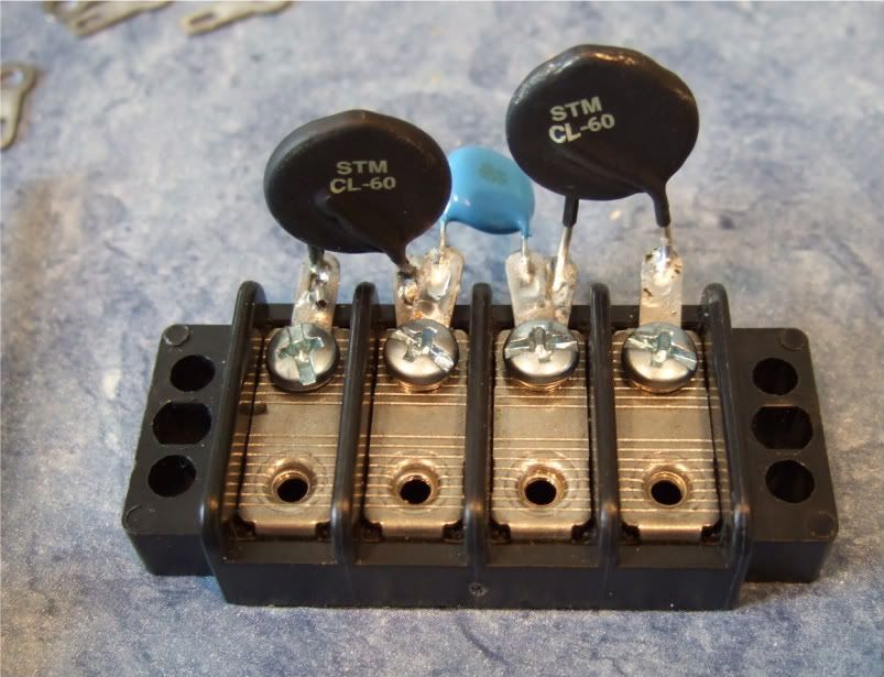
Here is the terminal block showing the thermistors and the capacitor.
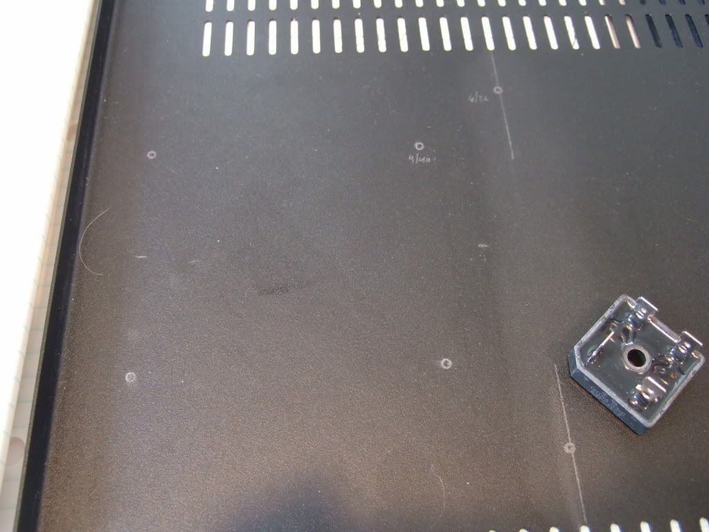
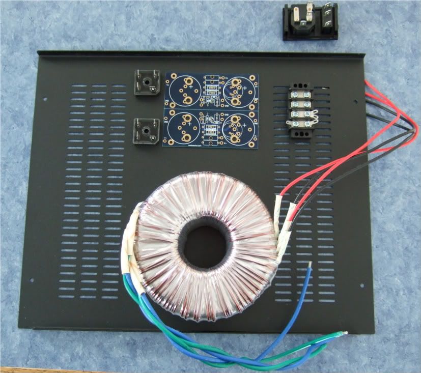
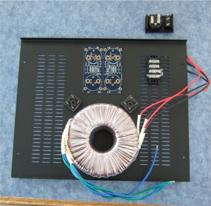
Marking the chassis bottom for the PSU board, rectifiers, and (not in photo) the transformer bolt.
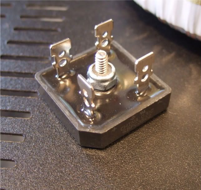
Rectifier block
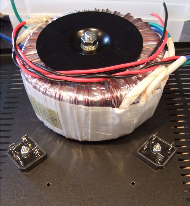
The monster Antek AN-6218
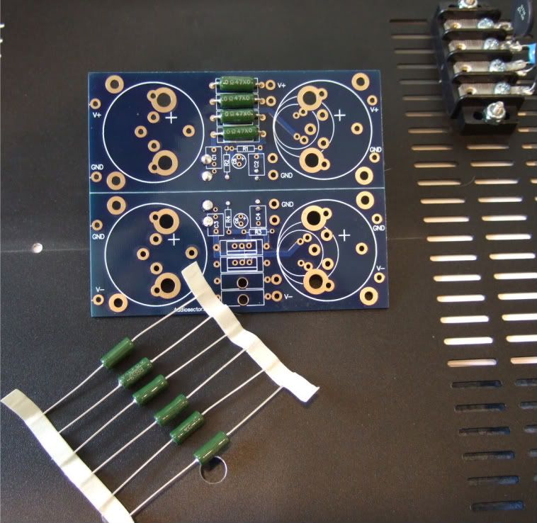
Stuffing the PSU board
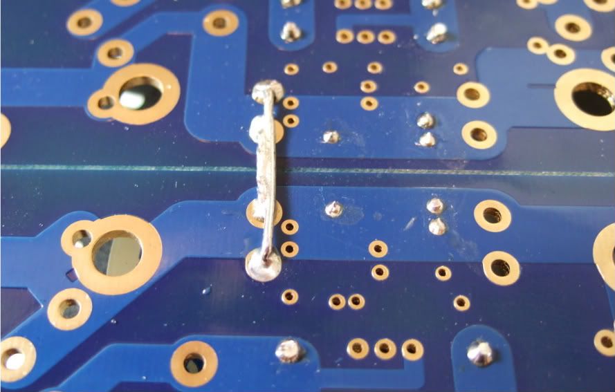
Remember to connect the grounds... Peter Daniel suggests you do it here. I am not sure if you need to have 2 jumpers like I am showing, but a good, low-impedance connection is always a good thing on a powersupply.
I mounted the bleeder resistors to the bottom of the board. You probably could do it on the top if you had physically smaller caps.
One thing that needs to be checked is if the spacers are taller than the bottom components. Looking good!
I needed to hold my camera upside-down to get the flash in a place where it could illuminate the bottom. This shows that there is plenty of room under the board.
The capacitors I am using.
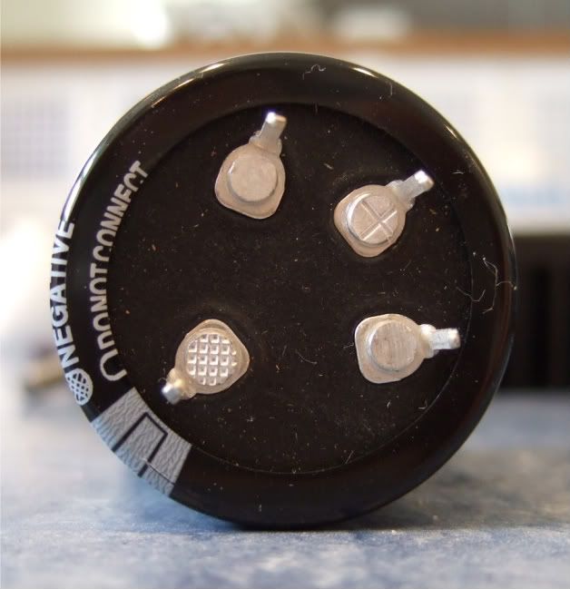
These are a 4-pin cap, and so the unmarked (and unconnected) pins need to be trimmed off.
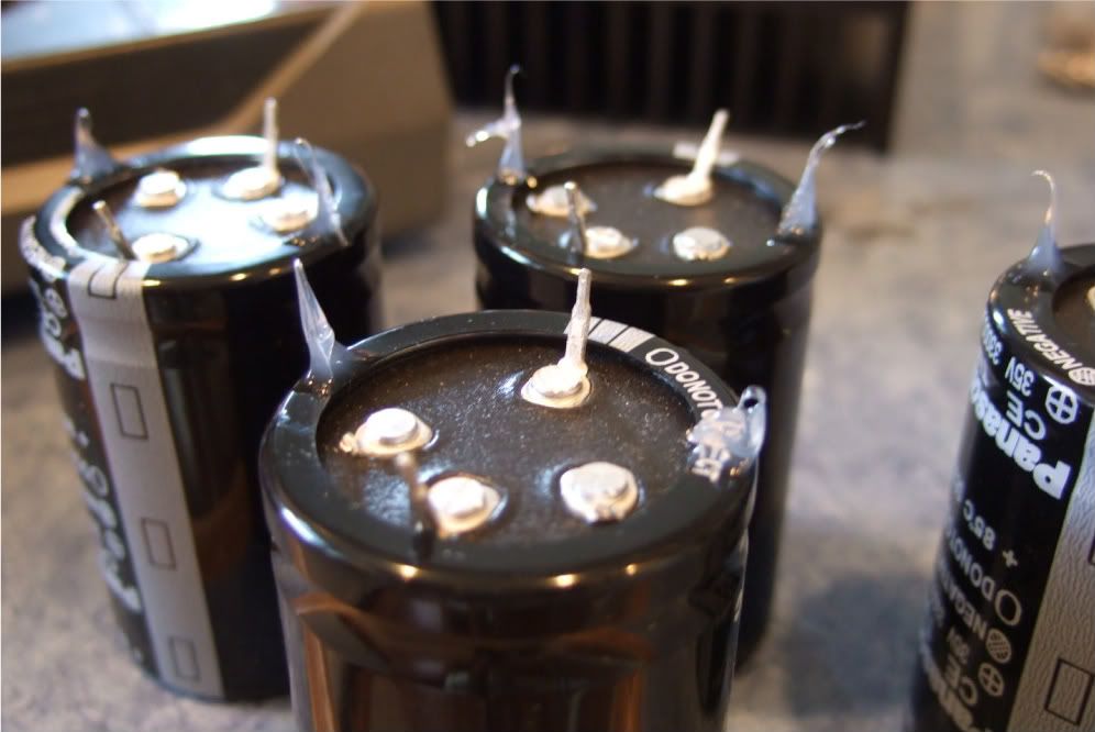
These caps are a bit big to be mounted just by two solder pins, so I am using just a small dab of silicone on the case to help stabilize and support the cans. Also note that the unused pins are now trimmed.
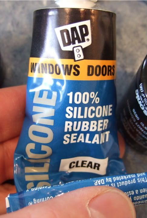
The silicone
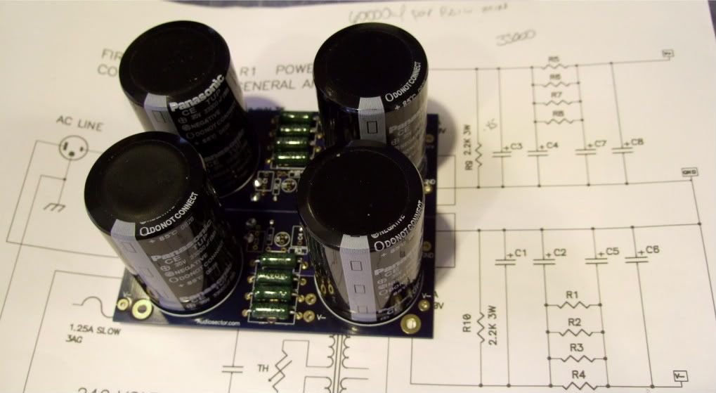
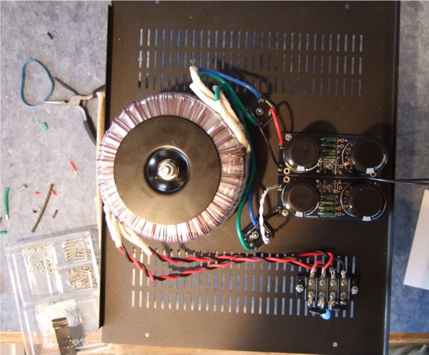
The complete (except wires) PSU board.
Wiring the PSU -
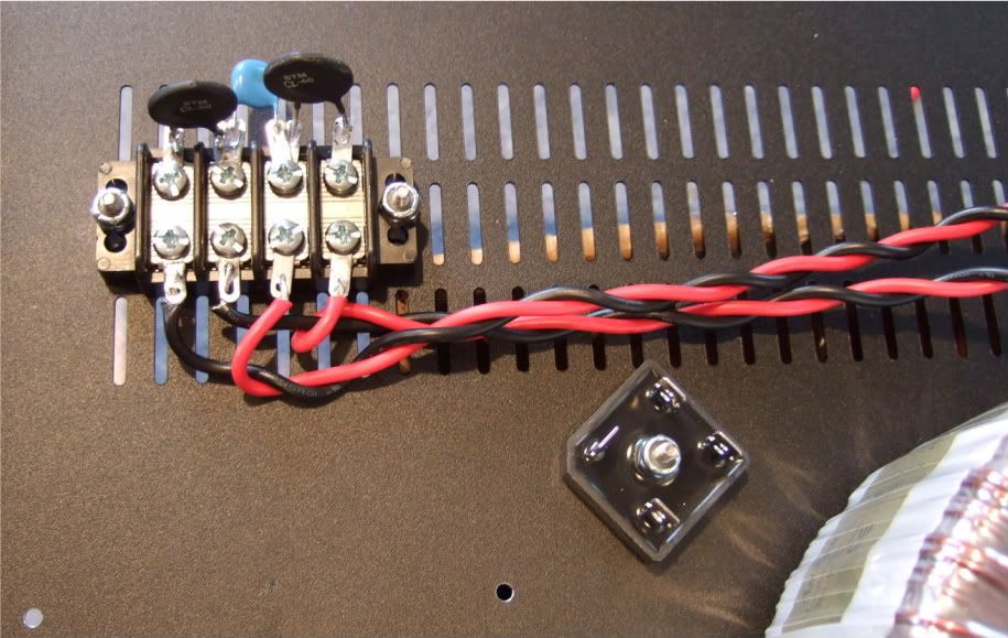
The primaries attached to the barrier strip. AC from the power inlet module will attach to the center two connections of the barrier.
Note the rectifier blocks -- the notched corner is "+" DC, it's opposite is DC "-" The other corners are AC in.
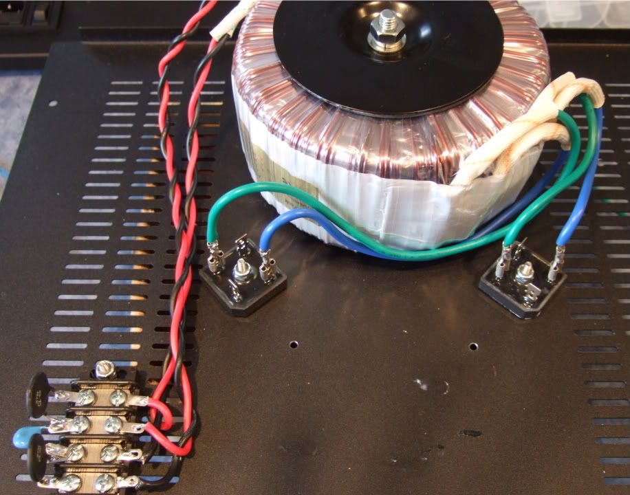
The leads of the secondaries connected to the rectifier blocks. Here you can see the AC connected to the AC in tabs of the rectifiers.
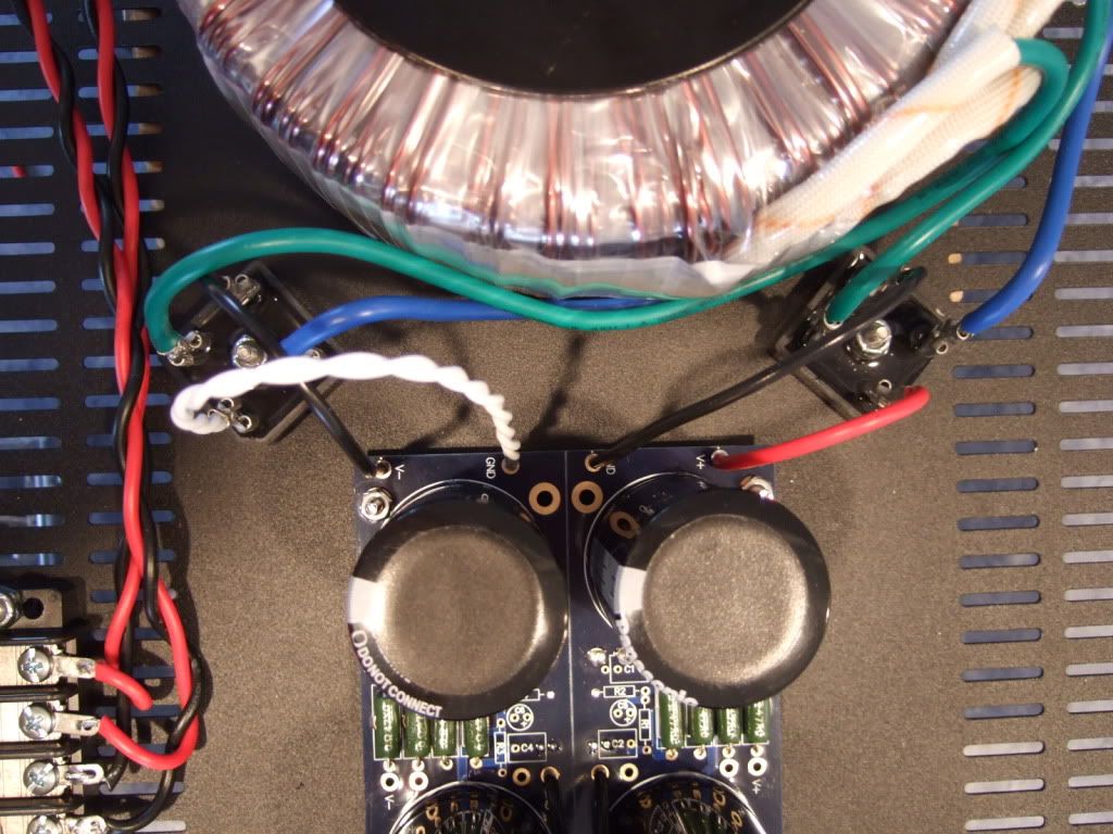
PSU board connected to the rectifiers.
The PSU completed except for AC in. This will be from the power inlet module. The black leads at the center of the PSU board will be the speaker negative connections.
Let's look at the PSU schematic just to make sure everything is OK... Remember that I am wiring it for 120v operation, so the transformer primaries are in parallel. People wiring for 240 with a transformer like this, please ignore.
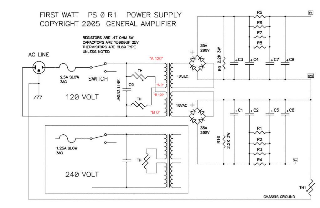
Notes in red are mine.
Look at the connections of the transformer primary, through the thermistors and line cap, to the mains.
Hot AC is connected to the "120" (which in my case is the red leads on the primaries) One red primary is connected to AC hot through a thermistor.
Neutral AC is connected to the black "0" leads, one of which is connected to the AC through a thermistor.
AC Hot and Neutral have a cap across the leads.
So, yes, the AC will be connected to the center 2 posts, which is across the cap.
Left to right we have post 1, 2, 3, 4
POST 1 - Transformer primary 'B 0' which will be connected to AC Neutral at post 2, through the thermistor between post 1 and 2.
POST 2 - AC Neutral in (not shown in photo), connected to Transformer primary 'A 0" , a thermistor to post 1, and a line cap to post 3
POST 3 - AC Hot in, connected to transformer primary "B 120", thermistor to post 4, and line cap to post 2
POST 4 - Transformer primary "A 120", connected to AC Hot through the thermistor to post 3
If you look at the red and black wires in the photo you will see that the Mains AC must to pass through a thermistor to connect to each of the 2 primaries. And that is the point of them, to keep inrush under control during powerup.[/QUOTE]
Thank you ,
Your pictures help a lots ;I have similar transformer fr Antek 625VA ,hesitated
to fire up ....until i triple check with yours(pic)
GOOD WORK
The original, if you are interested -- http://www.diyaudio.com/forums/pass-labs/182723-how-build-f5.html There are lots of neat questions and answers in that thread.
LOTS OF PHOTOS. IT WILL TAKE TIME TO LOAD THE PAGE.
Nothing out of the ordinary, Peter Daniel boards, single transformer, Tech-DIY transistors and other bits, HiFi2000 chassis.
I have collected all the pieces and finally today the chassis arrived from Italy! I am ready to start!
This is From Modushop.biz, it's a "Pesante Dissipante 4U depth 300 mm" (6 1/2" tall x 11 3/4" deep x 19" wide) Which will have a different specific number depending on color and faceplate thickness. I needed to get the shallow(300mm) case, if you have the room for it, you could get the 400mm deep.
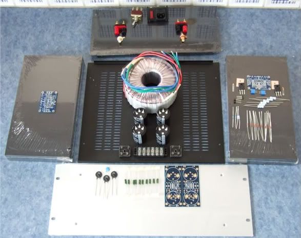
Here is the obligatory "armory" photo. Only one of the amp channels shown.
The rear panel. I thought I ordered an Inlet Module with a switch, but I didn't read the datasheet well enough, and it has a neon light power indicator instead. Oh well. Luckily I have a couple of nice bat-handeled switches, I will use one here. The Jacks and RCAs are also from my box, I think they are Vampire.
Here are the contents of the Tech-DIY F5 kits, the Peter Daniel's boards, and a couple of silpads.
The PSU components. Vishay rectifier blocks, Peter Daniel PSU board, resistors, 33,000uf capacitors, CL-60 thermistors, and a big-honkin' 600VA transformer.
When I was determining the transformer size necessary I must have had a brain-sneeze, I must have only thought of one secondary! Oh well, it was only $20 more than the 'proper' (400VA) size. The 4-pin caps will work on the board with just a bit of modification.
If you were wondering, the Peter Daniel boards are very small. Also very nice!
As mentioned earlier I needed to get a few more things before proceeding with the build…
Specifically, wire, connectors, standoffs, spacers, and a tap set. (also a couple of other things not photographed.)
As I am not exactly sure what will be the best standoff/spacer, I bought an assortment. Brass, Nylon, and 'real' 6-32 thread standoffs. Also shown are the 1/4" connector spades, the 6-32 bolts and fender washers for mounting the power transistors.
Also note the Power Inlet module now has a switch!
Not photographed is a big pile of 4-40 hardware for mounting the boards, as well as a few more 6-32 bolts for the rectifier blocks and barrier strip.
The store I went to didn't have taps without the drill bits, but since they are the exact size for the tap, I didn't see any disadvantage in getting them.
Trying to detemine the best layout for the bottom panel. The Transformer is positioned in the front of the case.
I like this better, it will lead to more symmetrical wiring. Which although not necessary, appeals to me.
If I had the 400mm deep chassis I would also have the power inlet and the barrier strip on the centerline.
I think it is a good idea to leave the chassis vents unobstructed, to keep the heat exchange/airflow as good as possible.
Today I got some drilling done. A lot of effort with not much to look at...
This is the amp board and the 2 power transistors. They will be mounted to the middle of the heatsink.
Once the hole locations are marked, I made some starter holes with a set punch. The 4 in the middle will be 4-40, the two on the outside 6-32
Drilling. Wear safety glasses!
Drilling complete.
My friend was kind enough to tap the holes.
Pilot holes for the RC jacks and Speaker posts. Also the beginning of the IEC inlet module cut-out.
I have all I need in place to build the amplifier circuit and mount it to it's heatsink -
Here is the heatsink, with the holes sanded smooth and cleaned with rubbing alcohol to remove the last oil and sandings/shavings.
Here is the hardware, 6-32 bolts and fender washers on the transistors, brass spacers and 4-40 bolts on the board
A dry run, to check fit.
Spacing looks good! Now to complete the board...
Stuffing the board. Have your meter at the ready and measure everything before soldering!!! It will save headaches later!!
OK, the board is stuffed and the wires attached. My color coding is as follows;
Black - ground
Blue (V-)
Green (V+)
Red (+) out
Red/black twisted pair in orange jacket is input + and -
I like to have the wires much longer than needed to help facilitate neat and tidy wiring later.
On the heatsink with silpads attached.
In this photo you can see the following -
The thermistors are not bent down yet, as I need to get some loctite for the threads before I am actually done... Same with the transistors, they are not soldered and trimmed.
The two 3W resistors on the outside of the PCB (R11 and R12) are standing up off the board so that when it becomes time to set bias, I can easily connect leads across the resistors.
Here is the terminal block showing the thermistors and the capacitor.
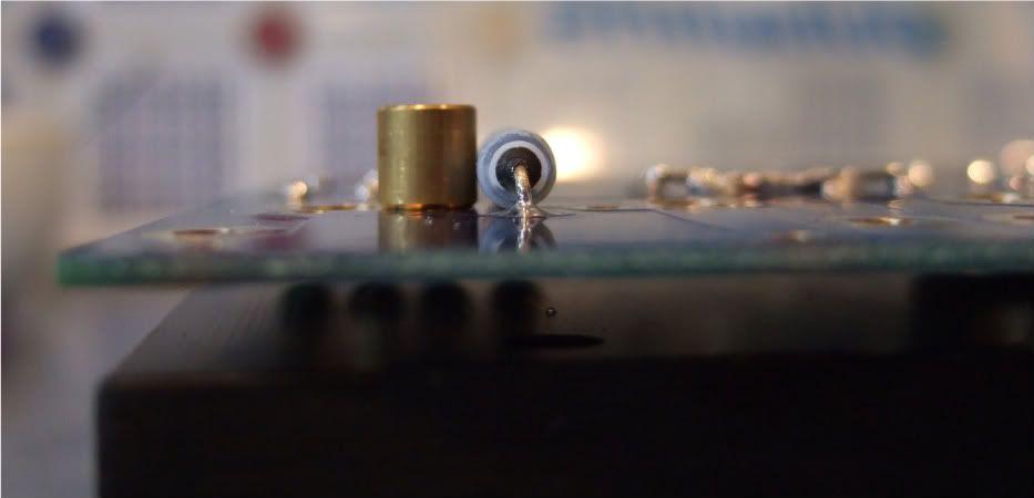
Marking the chassis bottom for the PSU board, rectifiers, and (not in photo) the transformer bolt.
Rectifier block
The monster Antek AN-6218
Stuffing the PSU board
Remember to connect the grounds... Peter Daniel suggests you do it here. I am not sure if you need to have 2 jumpers like I am showing, but a good, low-impedance connection is always a good thing on a powersupply.
I mounted the bleeder resistors to the bottom of the board. You probably could do it on the top if you had physically smaller caps.
One thing that needs to be checked is if the spacers are taller than the bottom components. Looking good!
I needed to hold my camera upside-down to get the flash in a place where it could illuminate the bottom. This shows that there is plenty of room under the board.
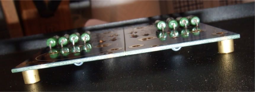
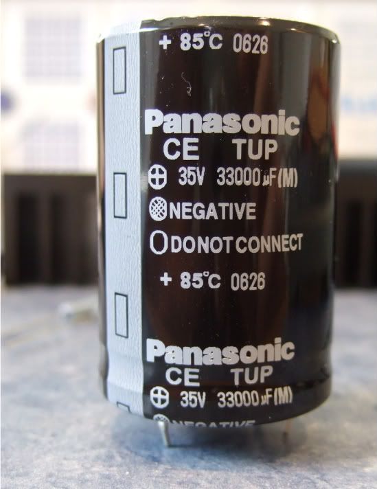
The capacitors I am using.
These are a 4-pin cap, and so the unmarked (and unconnected) pins need to be trimmed off.
These caps are a bit big to be mounted just by two solder pins, so I am using just a small dab of silicone on the case to help stabilize and support the cans. Also note that the unused pins are now trimmed.
The silicone
The complete (except wires) PSU board.
Wiring the PSU -
The primaries attached to the barrier strip. AC from the power inlet module will attach to the center two connections of the barrier.
Note the rectifier blocks -- the notched corner is "+" DC, it's opposite is DC "-" The other corners are AC in.
The leads of the secondaries connected to the rectifier blocks. Here you can see the AC connected to the AC in tabs of the rectifiers.
PSU board connected to the rectifiers.
The PSU completed except for AC in. This will be from the power inlet module. The black leads at the center of the PSU board will be the speaker negative connections.
Let's look at the PSU schematic just to make sure everything is OK... Remember that I am wiring it for 120v operation, so the transformer primaries are in parallel. People wiring for 240 with a transformer like this, please ignore.
Notes in red are mine.
Look at the connections of the transformer primary, through the thermistors and line cap, to the mains.
Hot AC is connected to the "120" (which in my case is the red leads on the primaries) One red primary is connected to AC hot through a thermistor.
Neutral AC is connected to the black "0" leads, one of which is connected to the AC through a thermistor.
AC Hot and Neutral have a cap across the leads.
So, yes, the AC will be connected to the center 2 posts, which is across the cap.
Left to right we have post 1, 2, 3, 4
POST 1 - Transformer primary 'B 0' which will be connected to AC Neutral at post 2, through the thermistor between post 1 and 2.
POST 2 - AC Neutral in (not shown in photo), connected to Transformer primary 'A 0" , a thermistor to post 1, and a line cap to post 3
POST 3 - AC Hot in, connected to transformer primary "B 120", thermistor to post 4, and line cap to post 2
POST 4 - Transformer primary "A 120", connected to AC Hot through the thermistor to post 3
If you look at the red and black wires in the photo you will see that the Mains AC must to pass through a thermistor to connect to each of the 2 primaries. And that is the point of them, to keep inrush under control during powerup.[/QUOTE]
In 6L6's diagram there appears to be a CL60 inserted between 'AC-input' ground and chassis ground, which I don't think is correct. CL60 is between star ground and chassis ground....?
Andersonix--sharp eyes and good point. You're right. You definitely don't want any resistance between the mains ground and the chassis ground (it's a safety concern)--but you DO want to have that in-rush limiter between the PSU ground buss, and the chassis....
6L6--you may want to confirm, and redraw your diagram, if need be.
6L6--you may want to confirm, and redraw your diagram, if need be.
In 6L6's diagram there appears to be a CL60 inserted between 'AC-input' ground and chassis ground, which I don't think is correct. CL60 is between star ground and chassis ground....?
You are absolutely correct. That will teach me to draw a diagram while there is a toddler in my lap, who is also trying to draw on daddy's paper!! 🙂
And as it is a remotely hosted image, I can edit it. 😀
Heck, 6L6--I'm curious what you used as CAD software for your diagram. It looks as though it's simple, easy to use, and something I could learn quickly!
F5 progressing...
Ok, I've solved my PSU related problems. I'm getting ~ + 25/ ~ -15 v out of the power supply.
I was able to work on a single channel today. I set P1 & P2 to ~ 0 ohms, greased the heatsink and mosfet, added the mica insulator between the heatsink / mosfet. Hooked up the wires, etc... I was ready to test it!
I used a 25Watt bulb on the power cable into the amp.
I hooked up 2 voltmeters to check for dc voltage on R11 & R12. I started the unit, it powered up and lit the bulb and led.
I was adjusting P1 & P2 clockwise, but I reached a max of .18v dc. (I know the service guide says .59v)
Any suggestions?
Last edited:
Very nice looking build! Also a big thank you for this thread. I am just finishing my F5 build and I encountered the same problem as you. Only able to get bias to 150mv with 0.01v offset and run out of travel on pot. Thankfully you had the answer to my problem. Changed R3 and R4 to 4.7kohm and now it is biased up to 600mv with 0.001v offset and room to spare on pots. I wonder how common this is?
- Home
- Amplifiers
- Pass Labs
- An illustrated guide to building an F5