Transformer problem solved... turned out my DMM was malfunctioning! What are the odds of that??
I actually got some sort of output now from the TDA using a 75ohm resistor to gnd yesterday, but it was horribly distorted. A sine wave from a test CD looked like a square signal, but something was moving.
I just tried again, and let it play for some minutes and after a while .......... a NICE CLEAN SIGNAL APPEARED !!!! 😀😀
Victory at last! This weekend I will rig up an output stage, and then I will finally get this baby going!
Needless to say, I am pretty pleased with this!
And while I am at it, I want to take this opportunity to thank Oliver for the Sunday morning session 2 weeks ago at his place. He mentioned it was his honour driving him, and he spent considerable time getting my dac boards going! So thanks to Oliver!! 🙂
It turned out that the problem in my boards were the small inductors on the board. These had (maybe through soldering, maybe through transport) stopped functioning. So this is one to check first if your board doesnt work, and avoid some sleepness nights
It turned out that the problem in my boards were the small inductors on the board. These had (maybe through soldering, maybe through transport) stopped functioning. So this is one to check first if your board doesnt work, and avoid some sleepness nights
Hey StudioStevus,
Glad you found the problem and finally got it working 🙂
Looking forward to your views on it 🙂
Alon
Glad you found the problem and finally got it working 🙂
Looking forward to your views on it 🙂
Alon
Finally
Hi Studiostevus, yes really good to hear that your baby is on the way to be a perfect DAC. Congratulations!
Ernst
Hi Studiostevus, yes really good to hear that your baby is on the way to be a perfect DAC. Congratulations!
Ernst
Hi Studiostevus
it is nice to hear you have solved you issues succesfully 🙂🙂
Because I still have my shunt regulator unsolved, it is interesting to know how you solved the transformer problem? Does high voltage input really influence on too high output or here was something else?
Now you will be happier and happier every day next week at least 😀 - I have experience that TDA1541 is going to "burn in". So be patient please...😉
For example my double crown was going onto it's real sound more than one month! I was playing mine Philips CD 960 at least few hours per day.
Best wishes for your weekend!
Will wait for review on your DAC.
it is nice to hear you have solved you issues succesfully 🙂🙂
Transformer problem solved... turned out my DMM was malfunctioning! What are the odds of that??
Because I still have my shunt regulator unsolved, it is interesting to know how you solved the transformer problem? Does high voltage input really influence on too high output or here was something else?
I just tried again, and let it play for some minutes and after a while .......... a NICE CLEAN SIGNAL APPEARED !!!! 😀😀
Now you will be happier and happier every day next week at least 😀 - I have experience that TDA1541 is going to "burn in". So be patient please...😉
For example my double crown was going onto it's real sound more than one month! I was playing mine Philips CD 960 at least few hours per day.
Victory at last! This weekend I will rig up an output stage, and then I will finally get this baby going!
Best wishes for your weekend!
Will wait for review on your DAC.
Hi Studiostevus
it is nice to hear you have solved you issues succesfully 🙂🙂
Because I still have my shunt regulator unsolved, it is interesting to know how you solved the transformer problem? Does high voltage input really influence on too high output or here was something else?
Now you will be happier and happier every day next week at least 😀 - I have experience that TDA1541 is going to "burn in". So be patient please...😉
For example my double crown was going onto it's real sound more than one month! I was playing mine Philips CD 960 at least few hours per day.
Best wishes for your weekend!
Will wait for review on your DAC.
There was actually nothing wrong with the transformer. Just my DMM was very consistent in displaying 46% more voltage than it actually measured. Hence, I thought it was 17V while it was a nice 12V. For the same reason I turned down the shunts until the DMM read 6V and I couldnt get lower than that. In reality they were giving only 4V...
So with a new DMM I could turn up the shunts, fiddle around a bit more, and voila!
Impressions on the DAC board mod...
The bypass mod on the DAC board is complete and I agree with the other posts that it made a positive difference in my system.
While the detail improved, the biggest change for me was the soundstage clarity (defined spaces for instruments and voices) and "analog smoothness". Unbelieveably good......
The bypass mod on the DAC board is complete and I agree with the other posts that it made a positive difference in my system.
While the detail improved, the biggest change for me was the soundstage clarity (defined spaces for instruments and voices) and "analog smoothness". Unbelieveably good......
Hello I a'm new to this forum.
I never thought i be still building DAC's at the age of 61.
I used D.D. spdiff and for USB i used from DAC's - www.pcm63.com - All For High Quality Audio DIY they have a USB
entry for just 15 dollar!!! both the entry's play without a buffer.
Sound is good, best i heard all my live!!
I never thought i be still building DAC's at the age of 61.
I used D.D. spdiff and for USB i used from DAC's - www.pcm63.com - All For High Quality Audio DIY they have a USB
entry for just 15 dollar!!! both the entry's play without a buffer.
Sound is good, best i heard all my live!!
Guys, good news.
We have lift-off!! I now also got my Pedja Rogic i/v stage going, and I finally (after 9 months) have music out of this thing.
... now happily burning in ...
We have lift-off!! I now also got my Pedja Rogic i/v stage going, and I finally (after 9 months) have music out of this thing.
... now happily burning in ...
Pedja Rogic i/v stage
Hi Studiostevus:
Do you have any pic for us about your Pedja Rogic i/v stage?
Thank you.
Hi Studiostevus:
Do you have any pic for us about your Pedja Rogic i/v stage?
Thank you.
Guys, good news.
We have lift-off!! I now also got my Pedja Rogic i/v stage going, and I finally (after 9 months) have music out of this thing.
... now happily burning in ...
Excellent 🙂🙂🙂
I have good news too - have fixed my [-15V] Salas shunt regulator (here was impossible to make regulation of output voltage).
As Oliver and me suspected - one 2SK170 was damaged.
However not the next to BC560, but one is "in charge" as CCS of reference voltage [two LEDs]) - you can see in attached picture which.
This damaged FET now is replaced and everything seems to be ok.
Attachments

Did anyone have yet the opportunity to to an AB comparison between this DAC and any others? I would like to know how it compares to
DIY-favorites, like buffalo etc.
Commercial competitors, e.g. weiss, benchmark dac1, audio note, etc
Anyone?
Do we have a 'reference dac' on our hands?
DIY-favorites, like buffalo etc.
Commercial competitors, e.g. weiss, benchmark dac1, audio note, etc
Anyone?
Do we have a 'reference dac' on our hands?
i'm going insane trying to troubleshoot this with one photo of the board (imageshack is down) and no schematic.
does anybody have a schematic for this thing????
does anybody have a schematic for this thing????
i'm going insane trying to troubleshoot this with one photo of the board (imageshack is down) and no schematic.
does anybody have a schematic for this thing????
Is attached in my Blog.

Is attached in my Blog.
Thanks for uploading that Oliver.
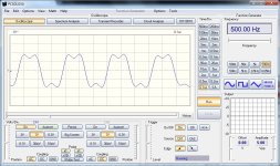
The BCK output from my Twisted Pear i2s converter is shown in the attached picture. Is it supposed to look that bad? Also it seems to have a fair bit of jitter. Also it is at about 3.07 Mhz instead of 2.82.
This trace is from the converter removed from the circuit and powered by 3 AA batteries, optical source. It looks the same while in the circuit.

Attachments
Last edited:
took some more screen shots, one with a persist trace showing BCK jitter and the second shows the frequency spectrum, which is quite messy. Lots of high order harmonics. Also the BCK frequency is 3.07 MHz.
So i think there is something wrong with my TP SPDIF board?
So i think there is something wrong with my TP SPDIF board?
Attachments
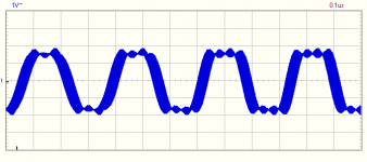
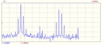
took some more screen shots, one with a persist trace showing BCK jitter and the second shows the frequency spectrum, which is quite messy. Lots of high order harmonics. Also the BCK frequency is 3.07 MHz.
So i think there is something wrong with my TP SPDIF board?
I don't think your SPDIF/I2S converter is damaged. 3,07 Mhz means only that it is running on 48kHz sample rate, not 44.1 kHz as from CD source.
Concerning long slopes in the trace of BCK -IMHO the point is that your osciloscope PCSGU250 has too narrow bandwith - for clear shot of 3.07 Mhz BCK you need bandwith about 50 - 60 Mhz, not 12 Mhz as you have.
And sampling rate also can be too low - even with 25MHz sampling you will "catch" about 8 samples per 3.07Mhz period. So 4 samples per half period only... really bad 🙄
There are some data of your oscilloscope:
◦bandwidth: two channels DC to 12 MHz ±3dB
◦time base: 0.1µs to 500ms per division
◦sampling frequency: 250Hz to 25MHz
- Status
- Not open for further replies.
- Home
- Group Buys
- "Reference" TDA1541A DAC with I2S-BUS architecture