It totally works !!!
....
10Khz square wave is still very fast .... but has a damped overshoot (below 2) ???😕 . Ran the 10R resistor into a big 10uF cap and the overshoot "ringing" was larger but still damped. Cold Zoble , total flatline (0 V) with no input , absolutely stable 12-14 mV Vbe even after temperature cycling. Without the load , there was no overshoot. Is this normal ?
OS
That's not ringing, it is a transient oscillation induced by the load + cabling inductance and the output capacitance of OPS (RLC circuit), ... unavoidable with a high dv/dt impulse, don't worry the amp behaves stable as shown on the scope.
Cheers
Arturo
I tried the amp at 60V p-p with no load , the slight overshoot is still apparent (below 1). The overshot edges are where the ringing occurs. Should there be no overshoot ? Driving the 10uF capacitor did not produce much more ringing (well damped). The slew in the pix is way over 80V/us (more like 100V+) , is this why I get the overshoot (too fast ??). The AX board has every compensation scheme designed into the layout. Extra pad for lead compensation (vas or NFB) , miller comp. , TMC , TPC ... everything (universal blameless). Maybe if I play with the TMC feedback or add a little lead comp ???? will play with it. Still a few parts short of final assembly , but I have major points nearly finished (a working amp) 🙂
OS
For me that shape is good enough, unless you like a sluggish over damped rounded response, that little overshot doesn't harm.
transient oscillation
That's a new one 🙂 So you say the wire + the nichrome 95W/10R resistor creates this errata ?? The "real world" is full of surprises. 😀
Cool !!
OS
sluggish over damped rounded response


But that is popular here at DIYA , I have seen so many square waves that have nice rounded edges. I guess it will all come down to sound quality ...
It (the amp) has been "burning" away for 3 hours now .. the resistor will sizzle water ... 😱😱 . the Nikko heatsink is just "warm" (amazing coefficient for a smallish heatsink).
OS
Last edited:
But that is popular here at DIYA , I have seen so many square waves that have nice rounded edges. I guess it will all come down to sound quality ...
It (the amp) has been "burning" away for 3 hours now .. the resistor will sizzle water ... 😱😱 . the Nikko heatsink is just "warm" (amazing coefficient for a smallish heatsink).
OS
YES, let it as it is, I bet it should sound very good (accurate trebles).
For "real music" material such high dv/dt impulses don't occurs, even when clipping so preserving 80V/usec slew the amp can reproduce the shape of a audible 10KHZ "complex" signal up to 10 or more harmonics, (the harmonic BW of a trumpet may rise to 200KHZ !!!), inaudible harmonics makes the difference in the sound (and good tweeters of course).
For "real music" material such high dv/dt impulses don't occurs, even when clipping so preserving 80V/usec slew the amp can reproduce the shape of a audible 10KHZ "complex" signal up to 10 or more harmonics, (the harmonic BW of a trumpet may rise to 200KHZ !!!), inaudible harmonics makes the difference in the sound (and good tweeters of course).
Some do not believe this. As they do not believe that a quality part can make any audible difference. What confuses me is that the "best" sounding amps (subjectively) .. DX , AKSA 55... DO NOT have this speed. Rounded SW edges , dominant second harmonics ... but they are acclaimed to be very musical. My last AX had the clearest highs that can be had , I just never (saw) why. My philosophy has been defined .... A bad design with quality parts will still be bad , but with pretty parts. A good design with mediocre parts will be as good as the parts. Rare in this world , but normal here at DIYA ... good design + good parts = WOW !! 🙂
BTW , is there a high power test load that can be run (built) that will NOT exhibit the transient oscillation ?
OS
O.
what happens if you move the C11 Cap (post 1635) to a position right at the bases of the driver transistors...??
what happens if you move the C11 Cap (post 1635) to a position right at the bases of the driver transistors...??
Hi Ost,
what filtering have you fitted to the input for your tests?
For music reproduction I think the bandwidth can be passively restricted to no wider than 1Hz to 200kHz. This is debatable and each designer/listener can set to suit.
For testing you might want to widen that by an octave or two at both ends, so that you can see better what the amplifier wants to do.
If you feed any amplifier with too fast a test impulse, it will overshoot. You have to decide what is "too fast" and what is a sensible "test signal".
Let's say you have a test filter with F-3dB @ 500kHz and the output is clean.
What happens if your test signal is unfiltered and you are effectively passing 10MHz harmonics with the fast test signal, through the front end of the amplifier?
O.
what happens if you move the C11 Cap (post 1635) to a position right at the bases of the driver transistors...??
C11 is decoupling for the Vbe. R86/87 are driver basestoppers. Moving C11 (to Q94/95 Bases) is contrary to any DIY design I have seen and all the OEM's ???? 😕
By andrew T. - what filtering have you fitted to the input for your tests?
For music reproduction I think the bandwidth can be passively restricted to no wider than 1Hz to 200kHz.
Heck with the online calc's or a paper calculation (below 1) is the whole LT plot of the input stage LP filter (390pF/33k).
It's F -3db is 470K ... so close to what you called for.
(below 2) is the bandwidth of the amp ... funny thing , the amp was relaying the 100kHz switching noise of the local large florescent ballast on the scope .. turned off the light , no signal/noise...
283KHZ as a -3db point ..... geez , no wonder the lights affected it ! 😱
Amp is still "alive" burning that 95W resistor with a 60V p-p SW all night ( can keep the coffee warm on that resistor 😀 ). heatsink is just warm with definite convection on the fins .... OP devices feel cool 😎 .
OS
Attachments
Last edited:
Some do not believe this. As they do not believe that a quality part can make any audible difference. What confuses me is that the "best" sounding amps (subjectively) .. DX , AKSA 55... DO NOT have this speed. Rounded SW edges , dominant second harmonics ... but they are acclaimed to be very musical. My last AX had the clearest highs that can be had , I just never (saw) why. My philosophy has been defined ....
Look I have years hearing "live music" (I am a sax player aficionado) I can discern when the tip of the stick hitting an AVEDIS ZYLDJIAN cymbal is metallic, plastic or wood, same for a clavichord, given a good recording this subtle sounds are partially masked or are difficult to hear when the amp is short of trebles, I know that the sound isn't as it should be, not good for me ... "Musicality" is a cultural and subjective sensation related to pleasure, brain loves some bias specially the 2nd harmonic, is like adding sugar to wine, for a bad wine maybe OK but certainly you would not like to add sugar to a fine good French or Chilean wine.
very difficult to build a real pure resistive load, physics reality check.BTW , is there a high power test load that can be run (built) that will NOT exhibit the transient oscillation ?
OS[/QUOTE]
Last edited:
I tried the amp at 60V p-p with no load , the slight overshoot is still apparent (below 1). The overshot edges are where the ringing occurs. Should there be no overshoot ? Driving the 10uF capacitor did not produce much more ringing (well damped). The slew in the pix is way over 80V/us (more like 100V+) , is this why I get the overshoot (too fast ??). The AX board has every compensation scheme designed into the layout. Extra pad for lead compensation (vas or NFB) , miller comp. , TMC , TPC ... everything (universal blameless). Maybe if I play with the TMC feedback or add a little lead comp ???? will play with it. Still a few parts short of final assembly , but I have major points nearly finished (a working amp) 🙂
OS
Hi OS
I disagree with a lot of the comments. What you had on the scope shot with the 10 ohm load was overshoot and ringing. I count 5 or 6 oscillations before it damps down, that is ringing. You should expect ringing when you parallel a 2uf cap with the load, but without the cap, it shouldn't ring. Also the nature of the ringing with the cap will be different, not a spikey ring, rather a rounded over ring. I'll post example an example picture. Regarding speed of the amp and overshoot or ringing; speed is not the issue with the overshoot and ringing. The speed should just give you a tighter square at the top and bottom of the wave form. The speed should help the amp turn the corner in a tighter radius, not shoot past. I have built current feed back amps that do 2000v/uS, they can be controlled and don't overshoot.
Ken
As I see the function of c-11.. it aids in holding the voltage (bias) spread on the drivers....Why not hold it right at the bases instead...In simulation it reduces distortion quite a bit...but could be that the parasitic capacitor elements can result i something undesired...
very difficult to build a real pure resistive load, physics reality check.
For power supply testing I had a test set that had a "carbon pile" (small "bricks" of carbon butted up against each other) load. As the pile warmed up I had to adjust the amount of physical pressure on it with a knob or the bricks would crack. I'm not suggesting you make one of these - but a load of non wire wound carbon resistors will result in less induction than the WW.
Buuuuuut that get's us into a discussion about how to really emulate a loudspeaker load - which has many things going on with it. WW voice coils present a large inductance as well back EMF with the swing of the signal - the resistance of the VC - some degree of capacitance - and that's all before we get into what's going on with the crossover network (if there is one). Some speakers are electrostatic or magnetic planer - and those present a different load to the amplifier.
For static testing I would go with a bank of non-wire wound carbon resistors. Of course you could always hook up speaker - but that can get really loud!!!! 😱
Hi OS,
I misspoke regarding the value for the cap that I used when testing, it was 1uf. The attached photo is amp running at just below clipping output into 4 ohms + 1uf. This is normal... without the cap the square wave doesn't ring or overshoot.
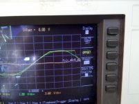
The other thing to test for is sticking when driven to clipping into a load. I don't know if you have Bob Cordell's book, but he very clearly describes what sticking and what to look for on the scope. My scope has math functions, so, I was able to scale the the output to match the input and difference them to see if it was sticking. It was... That's the second attached image. The yellow trace is the output running into clipping, the green trace is the input and the orange is the difference of the two. The bump at the end of the orange trace is the evidence of sticking.
Regards,
Ken
I misspoke regarding the value for the cap that I used when testing, it was 1uf. The attached photo is amp running at just below clipping output into 4 ohms + 1uf. This is normal... without the cap the square wave doesn't ring or overshoot.
The other thing to test for is sticking when driven to clipping into a load. I don't know if you have Bob Cordell's book, but he very clearly describes what sticking and what to look for on the scope. My scope has math functions, so, I was able to scale the the output to match the input and difference them to see if it was sticking. It was... That's the second attached image. The yellow trace is the output running into clipping, the green trace is the input and the orange is the difference of the two. The bump at the end of the orange trace is the evidence of sticking.
Regards,
Ken
Attachments
Last edited:
😱wowwwwwwwwwwwwwwwwwwwwI can discern when the tip of the stick hitting an AVEDIS ZYLDJIAN cymbal is metallic, plastic or wood, same for a clavichord, given a good recording this subtle sounds are partially masked or are difficult to hear when the amp is short of trebles, I know that the sound isn't as it should be, not good for me ... "Musicality" is a cultural and subjective sensation related to pleasure, brain loves some bias specially the 2nd harmonic, is like adding sugar to wine, for a bad wine maybe OK but certainly you would not like to add sugar to a fine good French or Chilean wine.

yeah, mid and tweeter adjustment does affect tuning on my bass guitar too
thats why a balanced sound(speaker) is crutial to make music sound right, and in tune
thats why a balanced sound(speaker) is crutial to make music sound right, and in tune
oscilloscope died , a few responses.
My DAMN CRO's sweep oscillator croaked. You can get both horiz. and vertical deflection on "X-Y" but the built in ramp generator that is the timebase is toast.
That's what I get for leaving that Ebay POS on all night 😡😡 .
I was about to explore this-
with slightly larger degeneration resistors and maybe some lead compensation applied to NFB. I guess I will have to use LT ... 🙁
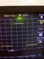
With the output of the amp DIRECT to the load (1uF/8R- below 1) I get " ringing" . With the output hooked to the L/C output network (below 2) (1.5uH/10R).. it goes away. 😕 I tested in the real world without the L/C , is it possible that this network negates the transient "errata"?? I sort of trust LT , but I have no scope now ... no other choice. Klewis , did your CRO test include the full output zobel/ inductor networks ???
BTW , the amp survived quite the abuse so far ... at least it is not unstable (cold as ice zoble). not the same for my POS scope 😡 .
PS .. I had to lower my input pair degeneration to 22R to get any sort of ringing (2mHz UGP).
OS
My DAMN CRO's sweep oscillator croaked. You can get both horiz. and vertical deflection on "X-Y" but the built in ramp generator that is the timebase is toast.
That's what I get for leaving that Ebay POS on all night 😡😡 .
I was about to explore this-
The speed should just give you a tighter square at the top and bottom of the wave form. The speed should help the amp turn the corner in a tighter radius, not shoot past. I have built current feed back amps that do 2000v/uS, they can be controlled and don't overshoot.
with slightly larger degeneration resistors and maybe some lead compensation applied to NFB. I guess I will have to use LT ... 🙁
With the output of the amp DIRECT to the load (1uF/8R- below 1) I get " ringing" . With the output hooked to the L/C output network (below 2) (1.5uH/10R).. it goes away. 😕 I tested in the real world without the L/C , is it possible that this network negates the transient "errata"?? I sort of trust LT , but I have no scope now ... no other choice. Klewis , did your CRO test include the full output zobel/ inductor networks ???
BTW , the amp survived quite the abuse so far ... at least it is not unstable (cold as ice zoble). not the same for my POS scope 😡 .
PS .. I had to lower my input pair degeneration to 22R to get any sort of ringing (2mHz UGP).
OS
Attachments
Last edited:
Hey , what do you guys think of these new ARM DSO pocket scopes ...
2Msps ARM DSO Nano Pocket Digital Oscilloscope 2.8" New | eBay
I see these from 30-140USD ???
OS
2Msps ARM DSO Nano Pocket Digital Oscilloscope 2.8" New | eBay
An externally hosted image should be here but it was not working when we last tested it.
.jpg)
I see these from 30-140USD ???
OS
With the output of the amp DIRECT to the load (1uF/8R- below 1) I get " ringing" . With the output hooked to the L/C output network (below 2) (1.5uH/10R).. it goes away. 😕 I tested in the real world without the L/C , is it possible that this network negates the transient "errata"?? I sort of trust LT , but I have no scope now ... no other choice. Klewis , did your CRO test include the full output zobel/ inductor networks ???
OS
OS,
Sorry to hear about your scope... Yes, my tests were with the full zobel/inductor network in place.
Ken
- Home
- Amplifiers
- Solid State
- The MONGREL (supersym II)