Nichicon FW, ES "muse for prosound" common applications
Well, don't forget the babies of the series. 🙂
They're useful bypass caps for larger caps, since they're too small for hf failure during the audio band. They're high efficiency, and they're 8 cents.
Nichicon FW 0.47uF 100v at Mouser
Nichicon FW 1uF 100v at Mouser
Especially for the ES, FW system, smallest electrolytic caps are potentially useful to patch up the HF response of larger caps. . . without putting any sudden peak into the impedance like a plastic cap *might* do (unless values of said plastic caps were 10x to 20x smaller so that they do less work).
Although a bit more than 8 cents, if you see NFB cap examples with something like 220uF//0.47uF its this: Nichicon ES 0.47uF 50v at Mouser used as a bypass cap to partner a larger size, ordinary grade, 220uF cap. That exact same thing works on the Via Tremor sound card outputs (those that ship with 220uF output caps).
Its all a really long winded way to say that the 470uF 100v FW might like a little 1uF 100v or 0.47uF 100v FW to complete its frequency response. . . . because there's probably nothing wrong with perfect, especially if that costs 8 cents.
P.S.
The ES, FW, "muse for prosound" products, are also often used as budget botique for speaker crossovers, because of the extreme high resolution in combination with rock bottom price. This use seems to apply directly to the amplifier for wherever the speaker return connects for ground (for whatever caps are nearest power star ground). 🙂
. . .I just bought the Muse's on mouser. . .
Well, don't forget the babies of the series. 🙂
They're useful bypass caps for larger caps, since they're too small for hf failure during the audio band. They're high efficiency, and they're 8 cents.
Nichicon FW 0.47uF 100v at Mouser
Nichicon FW 1uF 100v at Mouser
Especially for the ES, FW system, smallest electrolytic caps are potentially useful to patch up the HF response of larger caps. . . without putting any sudden peak into the impedance like a plastic cap *might* do (unless values of said plastic caps were 10x to 20x smaller so that they do less work).
Although a bit more than 8 cents, if you see NFB cap examples with something like 220uF//0.47uF its this: Nichicon ES 0.47uF 50v at Mouser used as a bypass cap to partner a larger size, ordinary grade, 220uF cap. That exact same thing works on the Via Tremor sound card outputs (those that ship with 220uF output caps).
Its all a really long winded way to say that the 470uF 100v FW might like a little 1uF 100v or 0.47uF 100v FW to complete its frequency response. . . . because there's probably nothing wrong with perfect, especially if that costs 8 cents.
P.S.
The ES, FW, "muse for prosound" products, are also often used as budget botique for speaker crossovers, because of the extreme high resolution in combination with rock bottom price. This use seems to apply directly to the amplifier for wherever the speaker return connects for ground (for whatever caps are nearest power star ground). 🙂
Last edited:
cap choices
For the power section , I chose to just use two 10 uF to 22uF's close to the 2 pair output devices. Typically , one would have the main "monster" PS caps no more than 6-8" away from either the power board or a full amp setup. Dr. Leach agrees with the Nikko and the JVC I have... as far as layout. Who am I to argue.
For the voltage section , I use a 100uF/100v decoupling along with a .1-.22uF poly. This then goes to the cap multiplier (220uF/100v) , and finally to a 22uF/.1-.22 FINAL decoupling array. All these have a common separate ground return to the main star. ALL the dual rail amps (separate OPS and voltage stage supplies) that I have seen use dual ground returns , even the single supply genesis amp had a separate ground for the low current part of the claas a output stage 😱.
The voltage stage itself has any CCS or cascode reference using the same return/decoupling as the cap multipliers. The input stage and NFB blocking cap is grounded through a 10R "lift " resistor. All this pays off in the end , absolute silence and great PSRR all around.
PS , on the full AX , I WILL include the pads for the typical 220u/.1-.22uf setup. 🙂 On my Nikko , my decouplers will be point to point so I can change them if needed.
OS
OS
Doc, please doc!
I believe it is time that for such a masterpiece some documentation is done. In the form of an Article, Manual, even Book, whatever you like.
Even for people like me that have followed and appreciated the developement from its beginnings, it might help to understad its caveats and its beauty. I am speaking about things like the difference between the three versions (i.e why the GX?) , the TMC choices, the cap multiplier.
I think this will give jour job the visibility that it deserves and help us learning.
Just my 2 Lire.
effebi
I believe it is time that for such a masterpiece some documentation is done. In the form of an Article, Manual, even Book, whatever you like.
effebi
This would be awesome and very much appreciated by many I'm sure!
Samwha
I have been eying the the Samwha electrolytics myself from Apex.
Are the caps HC's (2000hr @ 85 deg C) as shown in the image or
hopefully HL's (5000hr @105 deg C) ?

I have been eying the the Samwha electrolytics myself from Apex.
Are the caps HC's (2000hr @ 85 deg C) as shown in the image or
hopefully HL's (5000hr @105 deg C) ?
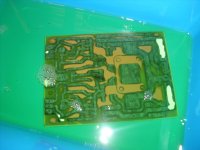
Man , this build is ( harder) whew !!
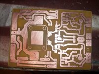
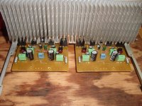
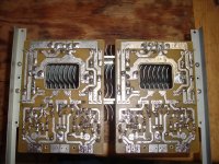
I etched and I etched till I could etch no more. 😀 (below 1)
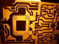
(below 2) The nikko power boards came out nice !! NO pits... (3)
Then ... will they fit , will they ventilate , will I have room to adjust bias ??
(below 4) is the tight emitter resistor/flyback diode zone which has to fit in the "tunnel" between the two heatsinks and the special high current interface next to the zoble network (left side).
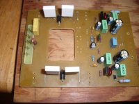
(below 5) is the front driver/cap multiplier/Vbe section with the trimmers...
(blue things in the middle) , being reachable from above.
and .. (below 6) was the hard part , putting those large vent holes in to allow the "tunnel" to have convection.
Am making some new AX1.3's with some special features now to plug into these power boards.
The PS's are done , as I have all new Mouser Nichicon 100v/105C caps (no chinese BS - MADE IN JAPAN ) Mouser states the country of origin. 🙂
OS
I etched and I etched till I could etch no more. 😀 (below 1)
(below 2) The nikko power boards came out nice !! NO pits... (3)
Then ... will they fit , will they ventilate , will I have room to adjust bias ??
(below 4) is the tight emitter resistor/flyback diode zone which has to fit in the "tunnel" between the two heatsinks and the special high current interface next to the zoble network (left side).
(below 5) is the front driver/cap multiplier/Vbe section with the trimmers...
(blue things in the middle) , being reachable from above.
and .. (below 6) was the hard part , putting those large vent holes in to allow the "tunnel" to have convection.
Am making some new AX1.3's with some special features now to plug into these power boards.
The PS's are done , as I have all new Mouser Nichicon 100v/105C caps (no chinese BS - MADE IN JAPAN ) Mouser states the country of origin. 🙂
OS
Attachments
(nearly) ready to go....
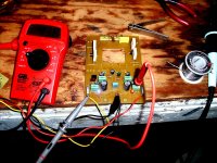
Cap multipliers work good (below 1) , scoped the OP with a loaded down PS with over 1 volt unrectified sawtooth ripple and the result was "flat line" (under .1mv multiplier ripple with a 220R load).
I always test individual sections out beforehand, as to have no surprises (solder bridges and such). Next , I hook up some AX modules and run just the Vbe and MJE 15032/33 drivers as a small amp. Adjust for 1.1V (+.55V and -.55v) between driver Re's and the outputs will NOT burn .
.
OS
Cap multipliers work good (below 1) , scoped the OP with a loaded down PS with over 1 volt unrectified sawtooth ripple and the result was "flat line" (under .1mv multiplier ripple with a 220R load).
I always test individual sections out beforehand, as to have no surprises (solder bridges and such). Next , I hook up some AX modules and run just the Vbe and MJE 15032/33 drivers as a small amp. Adjust for 1.1V (+.55V and -.55v) between driver Re's and the outputs will NOT burn
.OS
Attachments
Wow! There's no heat pooling.
I like your idea with the vent in the circuit board. It will make your amp last longer.
Question: Tall feet and a big air intake vent on the bottom of the enclosure?
I like your idea with the vent in the circuit board. It will make your amp last longer.
Question: Tall feet and a big air intake vent on the bottom of the enclosure?
Wow! There's no heat pooling.
I like your idea with the vent in the circuit board. It will make your amp last longer.
Question: Tall feet and a big air intake vent on the bottom of the enclosure?
I copied the original layout to the "tee". Except mine is on 2 PCB's with a 20mm gap between them (more ventilation). The bottom is about 20mm off the table with fully ventilated covers ... top and bottom. There is about 100mm of space left where the voltage modules mount as well. Another "feature" , is that the whole amp can be run outside the case ... you can drop it out the bottom for "tinkering" or adjustment.
Instead of the stupid way Nikko switched the speakers through the front "A/B"
panel buttons , I will make those same switches "fire" a pair of relays right at the back terminals. The front panel power meters and protection will be my next project. All this engineering will be ported to my "kits", as well. 🙂
OS
Relays? Sure. Well, it might be nice to have them switch off really fast, such as exactly at the same time as the power, rather than waiting on caps to drain. I don't know how to make a "slow on, fast off" circuit, but I'll bet you do.
P.S.
Front panel meters as an option? YAY!!! Those are fun!
P.S.
Front panel meters as an option? YAY!!! Those are fun!
4017 decade counter triggered into reset by multiple OR gates , when it goes through it's decade , it not only turns on the relay ... but gates the clock "off".
With 4 OR gates , any one can be a DC detect , overcurrent threshold , or turnoff trigger (as you suggested). All you would need is 2 quad OR gates (4071)
and a 4017 decade counter. 2 OR's will be a gated oscillator (clock) and the other 6 can be 2 4 input OR's. Hook appropriate Dc detect window comparators , over current circuitry and a turn off pulse circuit.... good to go. The 4017 will give a 5-10 second delay at initial turnon witha .5-1sec clock rate. ALREADY have built this - in 1987 even ( DIY amp when I was 21..... so it works ! 🙂
OS
Is it necessary to use a relay in audio path ??
Using a relay in transforme center tap will cut any DC in loudspeaker except capacitor charge .....
Using a relay in transforme center tap will cut any DC in loudspeaker except capacitor charge .....
4017 decade counter triggered into reset by multiple OR gates , when it goes through it's decade , it not only turns on the relay ... but gates the clock "off".
With 4 OR gates , any one can be a DC detect , overcurrent threshold , or turnoff trigger (as you suggested). All you would need is 2 quad OR gates (4071)
and a 4017 decade counter. 2 OR's will be a gated oscillator (clock) and the other 6 can be 2 4 input OR's. Hook appropriate Dc detect window comparators , over current circuitry and a turn off pulse circuit.... good to go. The 4017 will give a 5-10 second delay at initial turnon witha .5-1sec clock rate. ALREADY have built this - in 1987 even ( DIY amp when I was 21..... so it works ! 🙂
OS
Can you post a schematic and parts list here or on your website?
Can you post a schematic and parts list here or on your website?
Will post the logic/clock/relay section first , have not decided what to use to detect DC/overcurrent ... possibly the old TA7317 http://datasheet.octopart.com/TA7317P-Toshiba-datasheet-101460.pdf (2.99USD) ...
will simplify this design. Use it's output to toggle the OR gates. I am 30 years older now , I'm sure to do better this time around. 😀
OS
Is it necessary to use a relay in audio path ??
Using a relay in transforme center tap will cut any DC in loudspeaker except capacitor charge .....
That is a "smashingly" good idea. Just lift the LS ground returns from the main star. Audio goes direct.... If the amp shorted to a rail the speaker would be "live" , but you would have a protection event to deal with regardless. not too bad of a trade-off.
OS
And you will have a mighty power amp's central ground relying on a mortal relay contact for the rest of its serving life...
Is it necessary to use a relay in audio path ??
Using a relay in transformer center tap will cut any DC in loudspeaker except capacitor charge .....
Groundside noise is equal importance to input signal and there may be gain applied.
So, let's put the speaker relay at speaker + output instead.
I don't know if a relay is required at all, but its a very good question. OS?
This amplifier is designed for split-rail power--have a look at the schematic.
And you will have a mighty power amp's central ground relying on a mortal relay contact for the rest of its serving life...
Not mine , it has 2 grounds. My speaker returns are common with the local amp decoupling and zoble network. I was not thinking of the WHOLE central ground (trafo CT ??). My Voltage stage /drivers are on a totally separate DC supply with a separate ground return.
OS
Will post the logic/clock/relay section first , have not decided what to use to detect DC/overcurrent ... possibly the old TA7317 http://datasheet.octopart.com/TA7317P-Toshiba-datasheet-101460.pdf (2.99USD) ...
will simplify this design. Use it's output to toggle the OR gates. I am 30 years older now , I'm sure to do better this time around. 😀
OS
I have a more comprehensive datasheet for the TA7317P than the one you referenced. The file is too big to attach here; send me a PM if you want it.
That is a "smashingly" good idea. Just lift the LS ground returns from the main star. Audio goes direct.... If the amp shorted to a rail the speaker would be "live" , but you would have a protection event to deal with regardless. not too bad of a trade-off.
OS
Despite appearances, that's an ordinary single-rail amplifier, as you could assume due to the absence of the center tap.
Not good for AX.
Since AX is so very powerful, it seems both wasteful and possibly hazardous to waste the high current resources of center tap and earth ground.
So, please continue to use split-rail power and good grounding.
And, if you're hearing this from me? 😱
Last edited:
- Home
- Amplifiers
- Solid State
- The MONGREL (supersym II)