Pafi: No, it will improve with load because once the body diodes start conducting the miller stuff changes completely, it stops stealing so much charge from the gate.
Also, note that it's a phase-shift self oscillating design, high output current will only happen when the output goes close to the rails and switching frequency should be expected to drop a lot by that time, resulting in far more time for the gates to charge.
No doubt the design is very precarious, like in most subwoofer car class D amps. We can do more power with less MOSFET.
Pafi: No, it will improve with load because once the body diodes start conducting the miller stuff changes completely, it stops stealing so much charge from the gate.
How is this possible?
But it doesn't really matter, because turn on time counts only when the current direction is normal (form drain to source), so body diode doesn't conduct.
Also, note that it's a phase-shift self oscillating design, high output current will only happen when the output goes close to the rails and switching frequency should be expected to drop a lot by that time, resulting in far more time for the gates to charge.
If you mean high current is more then 60 A, then yes, but 30...50 A can flow at much lower voltage too. And the task is not only turning FET on at some time, but in a relatively insignificant time.
The miracle is: it works. I would like to know what the efficiency could be!
i replaced the irfp4229 with a pair of irfp264 i had and something must of happend cause i blew a KTA1837 ... maybe i should rebuild the driver board using new transistors ... i found that resistors that should have the same value are quite different so might have to deal with those to ...
it is preatty similar to this SONY XM-D1000P5 or am i wrong ? http://images.elektroda.net/78_1233429744.png
Ps: mgm2000ro measured the efficiency at 73% ...
it is preatty similar to this SONY XM-D1000P5 or am i wrong ? http://images.elektroda.net/78_1233429744.png
Ps: mgm2000ro measured the efficiency at 73% ...
Last edited:
VPPD is about 16V measured from vpp to vppd
Self-oscillating variable frequency closed loop Class D amplifier i think there is a patent on this schematic ...
Self-oscillating variable frequency closed loop Class D amplifier i think there is a patent on this schematic ...
There are probably one thousand patents on the same concept 😉
Concerning resistors, be aware that in many Chinese amplifiers and inverters they tend to be quite bad quality and resistance can change a lot with aging under high temperature or high voltage conditions. To make it worse, voltage ratings for each size are routinely exceeded on these products.
Concerning resistors, be aware that in many Chinese amplifiers and inverters they tend to be quite bad quality and resistance can change a lot with aging under high temperature or high voltage conditions. To make it worse, voltage ratings for each size are routinely exceeded on these products.
Last edited:
yes resistors and capacitors are very bad quality and i think they have changed theyer parameters ...
the Vppd is not regulated from what i can see ....
the Vppd is not regulated from what i can see ....
Vppd is not regulated, but entire smps is regulated.
In the scheme by Sony r191,192 = 390 ohm but is missing gate resistors.
Do you think that if we increase r191,192 at 390 ohm and reduce gate resistor from 100 to 20 ohm I will get rid of problems?
Excuse my English !
In the scheme by Sony r191,192 = 390 ohm but is missing gate resistors.
Do you think that if we increase r191,192 at 390 ohm and reduce gate resistor from 100 to 20 ohm I will get rid of problems?
Excuse my English !
Vppd is not regulated, but entire smps is regulated.
In the scheme by Sony r191,192 = 390 ohm but is missing gate resistors.
Do you think that if we increase r191,192 at 390 ohm and reduce gate resistor from 100 to 20 ohm I will get rid of problems?
Excuse my English !
Check for resistors with actual value outside tolerance range first.
I would also check DC current gains of Q110/Q111, Q114/Q116, Q118 and the low side NPN drivers (all the ones that run hot) with multimeter. The pairs should not measure very different.
Last edited:
I would also check DC current gains of Q110/Q111, Q114/Q116, Q118 and the low side NPN drivers (all the ones that run hot) with multimeter. The pairs should not measure very different.
I once had a fault where the transistor gain had been reduced to 1.
Of course it was the last transistor I checked !
You could use the output IRFP4227 is a good transistor. Post the complete schematic circuit for more details.
I once had a fault where the transistor gain had been reduced to 1.
Of course it was the last transistor I checked !
Same here, but happened in the LTP stage of a class AB amp. It took me forever to find out why the right channel was always a bit lower in volume and more distorted than the left.
And most people say those transistor gain testers on cheap multimeters were never of any use...
mgm2000ro gave me this ideea of a modification .. it implies using two separate 12V supplys for the totempole... one is referenced to -90V and the other one is referenced to output...
this should provide a clean square wave for outputs ..no ? what do you think.. ?
this should provide a clean square wave for outputs ..no ? what do you think.. ?
Attachments
mgm2000ro gave me this ideea of a modification .. it implies using two separate 12V supplys for the totempole... one is referenced to -90V and the other one is referenced to output...
this should provide a clean square wave for outputs ..no ? what do you think.. ?
Yes, this is the standard solution. But the question was: is it desirable to provide clean square wave in this circuit? I don't know the answer, because there are possible problems.
Have you find the wrong parts yet?
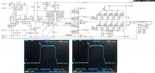
i just changed all the small transistors to MJE340/350 and ktc4793 to 2SC4793 and KTA1837 to 2SA1837 and the oscilating freq has doubled ...
Those two waveforms, modulator and driver out, look to be exactly the same signal.
I'd expect the frequency to increase with the + drive resistors gone, but double is going to ratchet up switching losses. Are you getting any cross-conduction?
I'd expect the frequency to increase with the + drive resistors gone, but double is going to ratchet up switching losses. Are you getting any cross-conduction?
Last edited:
- Status
- Not open for further replies.
- Home
- Amplifiers
- Class D
- GZPA Class D 4000W with IRFP264