If we consider a single channel (e.g. the first of the 10 channels of the mixer) with S7 switched on "Right" bus and consider also the wiper of Vr6 being in the lowest position (i.e., to ground) the total R is 32Kohm (parallel of 100K and 47k). Now, if all the 10 channels of the mixer have S7 switched on "Right" bus and Vr6 in the lowest position...we have a parallel of ten 32K resistors ... that is 3.2K ohm.
I still do not understand this. VR5 and VR6 are a single component, a dual gang potentiometer. If S7 is in position 3 then VR5 and VR6 act as a pan control. We also know the bus resistors are connected to a virtual earth i.e. we can assume they are connected to ground.
If the channel is panned right then VR6 is fully up and VR7 is fully down and vice versa. With VR6 fully up and VR5 fully down. The load from VR6 is VR6 (100K) an parallel with the 150K bus resistor i.e. 60K. VR5 is fully down so the load it presents is 100K in parallel with 47K i.e. 32K. The total load seen by V4 is thus 60K in parallel with 32K i.e. 21K which is OK. It does not matter how the other channels are set this is still the worst case load.
I think maybe you forgot about the bus resistors in your calculation.
S6 was a wrong reference. The exact component was S7! Neverthless... I think you have correctly interpreted the question. We inserted 1MR between S6-S7 and ground.
Yes, that is exactly what I meant !!
To be honest the 1M resistors are reported into the original Aikido schematic. We have not understood their utilities.
It seems they are 'safety' resistors:
New Tube Circuit: The Aikido Amplifier
Cheers
Ian
Virtual Earth Mixing With Tubes
Hi Antonio,
In have been thinking some more about your virtual mixing circuit and I think it has problems. I found an old simulation I did with an open loop gain of 20 and checked what it did with 10 inputs. As I had feared the gain drops (by about 4dB) and doubling the feedback resistor does not restore the gain. This really because the open loop gain is not high enough for the number of inputs. With op amps the open loop gain is so high you never really have to bother with this consideration but with tubes it is another story. I had a discussion about this four years ago on another audio discussion group where we concluded the maximum number of inputs you could connect to a virtual earth mixer was the open loop gain divided by 10 (to ensure there was always 20dB of feedback).
With your current design with an open loop gain of just 17 then you can really only have 1.7 inputs - not viable. For the 10 inputs you require you need an open loop gain minimum of 10 x 10 = 100.
Here is a link to the original discussion:
"Virtual earth" mixing amp with tubes
Cheers
Ian
Very bad news.
I read the discussion you mentioned ... but I did not find a possible solution in it.
Do you have a possible solution?
I read the discussion you mentioned ... but I did not find a possible solution in it.
Do you have a possible solution?
Very bad news.
I read the discussion you mentioned ... but I did not find a possible solution in it.
Do you have a possible solution?
I can think of two possibilities.
1. Increase the open loop gain to over 100. A design similar to the one shown by NY Dave would work - a pentode amplifier followed by a cathode follower. The pentode stage should easily be able to achieve a gain over over 100.
2. Change to passive mixing. You have 10 sources so the mix loss will be 20dB. You could use one of the SRPP stages to bring the level back up.
Cheers
Ian
The second solution seems simple. In any case we need of a tube stage (summing or SRPP).
The only complication (...that I can see) is the higher cross-talk (interference) in the passive mixer.
Indeed, several other limitations seems to be with resistive mixer (see Audio Signal Mixing) .
The only complication (...that I can see) is the higher cross-talk (interference) in the passive mixer.
Indeed, several other limitations seems to be with resistive mixer (see Audio Signal Mixing) .
The second solution seems simple. In any case we need of a tube stage (summing or SRPP).
The only complication (...that I can see) is the higher cross-talk (interference) in the passive mixer.
Indeed, several other limitations seems to be with resistive mixer (see Audio Signal Mixing) .
Both passive mixing and virtual earth mixing have their limitations and the article you linked to does contain some errors.
With passive mixing you need to minimise crosstalk and the interaction between controls.
There are several types of crosstalk in a mixer but the one most people think of is leakage from the L bus to the R bus (and vice versa). This mainly determined by the bus loss and the return loss via the channel source impedance. With 10 channels we know the bus loss is 20dB. Since we have taken care to include low output impedance buffers we know the channel source impedance is low - let's assume it is 1K. With 150K bus resistors this means the return loss is 150/1 or about 44dB. The cross talk is the bus loss plus the return loss i.e. 20 +44 = 64dB which I would say is more than adequate.
Interaction between controls depends on the change in the effective bus resistance as the control varies.
With the pan control wiper at ground its source resistance is zero. With it fully up the source impedance is that of the buffer amplifier or less than 1K. Somewhere towards the centre position of the pan control its source impedance will reach its highest value of about 15K. This is a 10% change in the bus resistance but because there are 9 other 150K resistors in parallel with it, it makes less than 1% change in the bus impedance and hence in the bus level. Since pan controls tend to be set and rarely moved, these small changes will rarely occur anyway.
Furthermore, none of the above applies to the vocal and bass channels because they are always fed from the low source impedance of the buffer.
Cheers
Ian
Ian,
you convinced us.
The web site I mentioned in the previous post terrorized and intimidaded us (about passive mixer).
We reconfigured the mixer circuit. Please have a look at it. In particular... verify that
- the pots and wiper resistors are correct;
- the 4 amplifier stages (gain=23 dB) are correct.
As to Vr5 and Vr6 ... What did you mean as "dual gang pot" ? ... a stereo pot with an inverted ground connection (signal up and ground down, in Vr5; signal down and ground up, in Vr6)?
Again ... we have not understood how you calculated the source impedance and the bus resistance.
Attachments
Ian,
you convinced us.
The web site I mentioned in the previous post terrorized and intimidated us (about passive mixer).
Unfortunately that web site contains some errors. The author states he does not know of any professional mixer ever using passive mixing. All the classic Neve mixers used passive mixing.
He says the worst case source impedance of a pot is half the pot value. This is incorrect; it is one quarter the pot value.
We reconfigured the mixer circuit. Please have a look at it. In particular... verify that
- the pots and wiper resistors are correct;
- the 4 amplifier stages (gain=23 dB) are correct.
The pots and wiper resistors look OK to me. I would add a 1Meg resistor from the grid of each of the four lower triodes to ground so that these tubes are biassed even if the bus is disconnected.
You also need to change S7 to a 3 pole 3 way switch and wire one pole for each of the bass, vocal and left/right destinations so that when they are not selected the bus resistor or pan pot is grounded. With passive mixing you must ground unused bus resistors - you cannot leave them floating.
As to Vr5 and Vr6 ... What did you mean as "dual gang pot" ? ... a stereo pot with an inverted ground connection (signal up and ground down, in Vr5; signal down and ground up, in Vr6)?
Yes, that is exactly what I mean.
Again ... we have not understood how you calculated the source impedance and the bus resistance.
The minimum source impedance is when the resistance from the wiper to either end of the pot is equal. With a normal pot this is at the half way point so a 100K pot has 50K up and 50K down. As the top of the pot is normally connected to a very low source impedance, the effective source impedance of the pot at the mid point is 50K in parallel with 50K or 25K i.e. one quarter the pot value.
The pan pot is more complicated because of the 47K slugging resistor but the equal resistance up/down point is at about the 30K down 70K up point. The 70K up in parallel with the 47K resistor is about 28K. This in parallel with the 30K down is just under 15K.
The bus resistance is simply the value of all the bus feed resistors in parallel. Since each one is fed from a very low source resistance then each bus resistor effectively feeds into N-1 bus feed resistors in parallel to ground. A simple bit of maths shows that the attenuation is N when N is the number of sources, in your case 10 or 20dB.
Hope that makes sense.
Cheers
Ian
Ian,
first of all ... have a Happy New Year.
Second ... thank you very much for your precious lessons.
Now we can talk about the schematic.
We have updated the schematic (see enclosed file). We believe it is correct, now. However, we are note sure about 3 previous 1M resistors (2 from the first two ways of S7 to ground and 1 from S6 to ground) and about the connection between S6 and ground too.
The 1M resistor to ground on the grid of the tubes downstream of buses could replace their function.
In the current schematic, all these doubtful components are reported in red.
Attachments
Last edited:
We have updated the schematic (see enclosed file). We believe it is correct, now. However, we are note sure about 3 previous 1M resistors (2 from the first two ways of S7 to ground and 1 from S6 to ground) and about the connection between S6 and ground too.
The 1M resistor to ground on the grid of the tubes downstream of buses could replace their function.
In the current schematic, all these doubtful components are reported in red.
To avoid clicks when operating switches it is essential to ensure that coupling capacitors like C13 always have a path to ground. At the moment, when the mute switch is operated, C13 no longer has a route to ground so you should add a 1Meg resistor from the right hand side of C13 to ground.
The 1 Meg immediately to the right of S6 is now not needed. The other towo 1Meg resistors are OK and S7 looks correct.
The only other thing is that C10 and C11 could also cause clicks when S5 is operated. The normal way to prevent this is to connect a high value resitors (4.7Meg will do) between the right hand end of C10 and the right hand end of C11.
Wishing you a Happy and Peaceful New Year
Cheers
Ian
Ian,
we are planning to realize the first layout of the circuit.
The blue board (see the enclosed schematic) has already been tested ... and both sections (Vu-meter and output for monitors) seem to work properly. In next days we'll test the remaining sections, but we need of several days (7-10 days) because we have to order several components that we do not have.
After a careful analysis of the schematic we noticed that the last section (V4, i.e., the cathode-follower of Aikido), after all, could be replaced by the previous one (V3), by simply changing the output point of C9 (from the anode of the bottom section of V3 to the cathode of the top section of V3).
In this case, two functions should be adapted: "the fader" and "the 75Hz low cut".
The first one (fader) could be included into the bus section (but we do not know if this may represent a problem for the source impedance of the passive mixer).
The last (75Hz low cut) could be solved by adding S5 and C10 after V1 (if "75Hz low-cut" is necessary only for microphones but not for instruments).
Which is your opinioin about that consideration?
Attachments
After a careful analysis of the schematic we noticed that the last section (V4, i.e., the cathode-follower of Aikido), after all, could be replaced by the previous one (V3), by simply changing the output point of C9 (from the anode of the bottom section of V3 to the cathode of the top section of V3).
In this case, two functions should be adapted: "the fader" and "the 75Hz low cut".
The first one (fader) could be included into the bus section (but we do not know if this may represent a problem for the source impedance of the passive mixer).
As you say, moving the fader to the bus section will be a problem for the source impedance of the passive mixer. V4 is essential for passive mixing.
The last (75Hz low cut) could be solved by adding S5 and C10 after V1 (if "75Hz low-cut" is necessary only for microphones but not for instruments).
Which is your opinioin about that consideration?
Yes, this would be OK.
Cheers
Ian
Ian,
after a (relatively) long time, we are returned to the mixer project.
We are now ready for the first step. We should realize the PCB and then to test the first prototype. Before the PCB realization we’d like to carry out a final check. We included the revised schematics. In particular, 5 specific questions would like to submit.
1) We have added a 300 ohm resistor on the grid of V5, V6, V7, V8 tubes in the bus-mixer section. Is it correct?
2) Could you verify if the section “a“ of TL082 is correct ? … are there any problem to drive the 4 lines ?
3) As to the anodic power supply … is the preliminary schematic correct ? Specifically, C1-L1-C2 will be included into the power supply section (located far from the preamplifier sections); while, the nets R1-C3, R2-C4, R3-C5, … will be located on the preamplifier-mixing boards, near the tubes. Is the double pi greek filter (C1-L1-C2-R1-C3 ... C1-L1-C2-R2-C4 ... ) adequate for a good anodic supply?
4) As to the top panel of the cabinet (where to mount the knobs, switches, faders, etc) … we have not yet decided which solution to adopt. The choice is between plastic and metal panel. Which solution is the best in your opinion ?
5) As to the connections between the preamplifier boards and the top panel we have organized the connections in the following mode:
- 1-way -> 1 wire-coaxial cable (with the wire gauze connected to the ground)
- 2-way -> 2 wires coaxial cable (with the wire gauze connected to the ground)
- 3-way -> 3 wires coaxial cable (with the wire gauze connected to the ground).
All earth returns (negative) are performed by a dedicated wire of coaxial cables (and not through the gauze). Is it correct?
Ciao
Antonio e Francesco
Attachments
Last edited:
Ian,
after a (relatively) long time, we are returned to the mixer project.
We are now ready for the first step. We should realize the PCB and then to test the first prototype. Before the PCB realization we’d like to carry out a final check. We included the revised schematics. In particular, 5 specific questions would like to submit.
1) We have added a 300 ohm resistor on the grid of V5, V6, V7, V8 tubes in the bus-mixer section. Is it correct?
That is a wise precaution. Make sure the resistor is as close as possible to the grid pin of the tube.
2) Could you verify if the section “a“ of TL082 is correct ? … are there any problem to drive the 4 lines ?
The total load might be a potential problem for TL062. Your worst case load is four 10K pots in parallel with four 10K resistors i.e. 1K25. The data sheet seems to imply the TL082 will drive loads lower than 1K so it should be OK in theory but I have no idea what will happen to the distortion. It might be better to increase the pots and resistors to 22K thereby making the worst case load 2K. With this load, the output capacitor C15 has a low frequency 3dB point of about 6Hz. It might be worth increasing C15 to 47uF.
3) As to the anodic power supply … is the preliminary schematic correct ? Specifically, C1-L1-C2 will be included into the power supply section (located far from the preamplifier sections); while, the nets R1-C3, R2-C4, R3-C5, … will be located on the preamplifier-mixing boards, near the tubes. Is the double pi greek filter (C1-L1-C2-R1-C3 ... C1-L1-C2-R2-C4 ... ) adequate for a good anodic supply?
Keeping the smoothing inductor well away from the preamps and the placing the local decoupling at the preamps themselves is a good idea. I have never used a C-L-C filter in a preamp power supply so I cannot say if it will be good enough.
4) As to the top panel of the cabinet (where to mount the knobs, switches, faders, etc) … we have not yet decided which solution to adopt. The choice is between plastic and metal panel. Which solution is the best in your opinion ?
Metal definitely and preferably aluminium. You can get very professional looking panels made by Schaeffer in Germany:
Front Panel Designer*- Schaeffer AG - Frontplatten, Front Panels, Faces Avant
5) As to the connections between the preamplifier boards and the top panel we have organized the connections in the following mode:
- 1-way -> 1 wire-coaxial cable (with the wire gauze connected to the ground)
- 2-way -> 2 wires coaxial cable (with the wire gauze connected to the ground)
- 3-way -> 3 wires coaxial cable (with the wire gauze connected to the ground).
All earth returns (negative) are performed by a dedicated wire of coaxial cables (and not through the gauze). Is it correct?
That is correct. In most cases you should aim for no signal current to flow in the screen (gauze).
Cheers
Ian
Antonio,
I forgot to mention in my last post, I think you have the 20dB pad in the preamp section connected backwards.
Cheers
Ian
I forgot to mention in my last post, I think you have the 20dB pad in the preamp section connected backwards.
Cheers
Ian
Antonio,
As a PA operator for over 30 years I would like to offer some opinions.
When starting out, I had to build everything, speakers, amplifiers, mixers, cabling.
There is no way I would do it now.
Most PA gear comes down to cost.
I have worked with dual systems, and theatre systems with multiple channels. I would normally go for a single system of the highest quality you can afford. If you spent that money on 2 systems, the result is most likely to be worse, there is more gear, more wiring, and a greater problem of earth loops, hums and noises. The setup time would be longer, transportation more difficult.
All of these things are an impediment to the main purpose - getting the music to people.
Most of the audience will not notice the subtle improvements in the sound quality.
The main objectives of PA gear are in order of importance:
1 Reliability
2 Reliability
3 Reliability
4= Suitable SPL for venues
4= Easy transportation
4= Sound quality
4= Ease of use
Without being prejudice to you, building gear fails on Nos. 1-3 and possibly ease of use. It will be a prototype. The amount of time and energy you will expend making a valve mixer suitable for live PA will not be worth it. It takes a highly skilled engineer to be able to design proper hum free earthing for the internals of a mixer. MANY manufacturers get this wrong. I and techs I know have had to modify $25,000.00 plus mixers to stop them humming!!
Any difficulties or impediments that a sound system causes a band saps their energy and enjoyment and degrades their performance.
I suggest you get advice and buy quality gear and learn how to do quality sound with it. That is a lifelong pursuit!!!
I believe that the reasons for such deterioration are essentially two:
1) The use of solid state devices employing many (too much) components in the signal path.
2) The common output.
As to the deterioration points:
1) It's the quality of these devices and implementation that matter. Most recordings have passed through up to 10 times as much circuitry as a PA has.
2) This is also a question of quality and headroom. A number of low quality systems as separate channels will sound better than one low quality one.
In my opinion the following items are the main reasons why people get poor quality sound and light gigs.
1) the sound engineer, either insufficient skill, they had no appreciation for music, order can be bothered doing a decent job.
2) the band aren't playing very well or the stage equipment is poor quality. Is no way you can get a decent sound if the band don't play properly. I think it takes quite a while to musicians to get high quality sound from their instruments and some of them never really achieve it.
3) the band are too loud on stage. This is a major problem. The sound that comes off the stage directly from the band is often really poor quality because it is not properly mixed, the volume levels are all over the place, and the acoustics of the stage are often a problem anyway. the quality get the band the better the sound is going to be end of possible get the van to use any monitor systems so the on stage sound can be really quiet. The combination of instrument amplifiers drums and monitor which is to reduce a cacophony of poor quality sound projecting itself into the audience.
4) poorly set up PA systems. Often the PA is poorly set, the speakers can be in a bad place, the microphones are often not ideally positioned, the mixing console is in a bad place, the levels and crossovers are not properly set the EQ isn't properly done. At times, it has taken me an hour and a half just to fix up the set up and a system that was supplied to me and is ready hand going he queued set up and everything some people just don't do a very well.
5) poorer quality equipment. As I'm sure you know, for quality equipment is going to produce poor sound. The most important elements of any PA system are the transducers, if you don't have good microphones and good quality speakers no work you do electronically will ever fix it. There is a lot of sound on the stage and every microphone will pick up all of sound. Cheaper microphones sound good when you address them directly in front but can have serious frequency anomalies when the sound arrives from other directions. This means that the generals stage sound is badly affected by arriving off axis entered all of the microphones on stage. There is no way to get rid of this horrible sound and it affects the whole quality of the mix. The speakers can also create a problem in that most of them vary quite a bit in the directionality of the different drivers and at different frequencies.quality speakers, on the other hand, have far more consistent directivity vs frequency, therefore the sound would be much more consistent throughout the room.
6) the other problem is the room. Often band's plan rooms are acoustically very poor, often over reverberant, and this makes it very difficult to get a quality sound.
Marcus.
Jan,
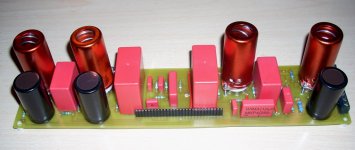
We took a long time but we have (finally) realized the first board (see the enclosed photo).
We have not yet tested it because we have some indecision about the heater power supply. We’d be very grateful if you could read our considerations and the solutions proposed. In any case, if a better solution exists, please don’t esitate to ignore our suggestions.
Considerations:
1) In order to reduce hum, AC heater supply should be avoided.
2) A soft start circuit should be implemented in order to avoid stressing conditions to the tubes in the first seconds after switching on.
3) Each cannel includes 4 E88CC tubes. We believe that it should be a good thing to have a power supply that, in the case a filament of a tube is broken, the entire channel should be disconnected (in order to avoid damage to the tubes due to the anodic power supply).
4) The cathode-filament voltage of each section of E88CC must not exceed the limit of Vkf reported in the data-sheet of the tube (http://www.mif.pg.gda.pl/homepages/frank/sheets/163/e/E88CC.pdf).
Possible solutions:
1) DC heater supply seems to be the more appropriate solution. In this view, non-stabilized power supply seems to be less advantageous because it imposes the adoption of a specific voltage for the transformer. Conversely, a stabilized DC supply allows to utilize a wide range of transformers (and we could have some). Could a series (6.3 x 4 = 25.2 V) stabilized (e.g. LM 317) heater supply be suitable?
2) If a stabilized DC heater supply results to be (in your opinion) a good solution … Could a LM317 with a transistor (on the adj pin) do the work? For example … adding the following solution (Soft Start Power Supply with IC LM317 and L200 | Circuit Project Electronic ) in a general LM317 high current power supply circuit like this (10A 1-30V Variable Power Supply with LM317 ).
3) If the consideration made is correct … could you suggest a simple circuit (that we should multiply by 10 …channels) doing what requested ?
4) According to the data-sheet, the Vk+/f- is 120 V and the Vk-/f+ is 60 volt. In our case, with 250 VRMS of anodic supply we should have about 120 V on the cathode of the top section and 4 volt on the cathode of the bottom section of the tube. So, the DC elevation of negative heater supply seems to be not necessary (120-25.5 = 94.5V; 4-25.4=-21.5). Is it correct?
Attachments
Hi Antonio (& son),
Good to hear from you again. That is a good looking PCB. Well done.
Answers to your questions:
1. I agree a dc heater supply is best.
2. A soft start for the heater supply is not normally necessary. However, if you use semiconductor rectifiers for the HT then this supply could be up before the heaters have fully heated and this could lead to potentially damaging voltages on the tubes. So it you need a soft start supply it would be for the HT and not the heaters.
3. I am not sure this achieves what you want because all the tubes will have no heaters but they will still have full HT. I would suggest you supply the heaters to the tubes in pairs at 12V then if one tube fail at most one other tube is at risk. probably the simplest way to do this is with a 7812 regulator for each board.
4. Your Vkf calculations need to include the signal. If the largest signal is 20V rms then this can increase the 120V cathode voltage by nearly 30V to say 150V.
Cheers
Ian
considerations
ok for points 1 and 2.
As to point 3, we think that a 25.2 Volt regulated supply (all the filaments of the 4 tubes of each channel in series) with a current sense control (on the heater supply) driving a relay switching-on the anodic supply should be fine and relatively simple to realize.
We were thinking a simple circuit like that reported in figure, but the LT1637 is not simple to find. Probably a simpler circuit is possible but we do not know it. Do you have some suggestion about a simple circuit to drive the relay switching the anodic supply?
As to point 3, indirectly you suggest to use a resistive divider on the anodic supply. What about the schematic reported in figure? From the data sheet of the E88CC it results that the Rk-f must be no more than 20K. So we adopted a resistive divider with R1=60k and R2=20K. In this way, with 250 anodic voltage, we should have 62.5 volt on the negative of the filaments (and only 3 mA loss in the resistors).
Attachments
Last edited:
Hi Antonio,
I agree with your resistive divider. I use one in my designs but because I use a different tube the resistor values are different. Remember to ensure the resistors can safely handle the power dissipation (about 800mW if my calculations are correct). You should also add an electrolytic capacitor of 47uF to 100uF as well as the 0.1uF you already have to keep power supply noise out of the filaments.
Regarding the current sense, the circuit you show is essentially a comparator which senses the voltage across the 0.2 ohm resistor. I can see nothing special about the circuit so almost any comparator will do - you do not need to use that particular chip.
If you want a really simple circuit then you could simply use the base emitter junction of a transistor instead of the comparator. It is only necessary to ensure when the tube filaments are on that there is enough voltage drop across the sense resistor to turn the transistor on (1V would be plenty) but you would have to increase the supply voltage by this amount. The transistor would then drive the relay directly. Bear in mind this is just an idea and I have not tested it.
Cheers
Ian
- Status
- Not open for further replies.
- Home
- Live Sound
- PA Systems
- Tube mixer