I was thinking of the 800V types it seems.
Been into tubes before?
With PP one can't go wrong generally.
Hannes
Hi
This is my interpretation of the wiring of the boards. Have I drawn it right or have I got it backwards?
Even though the picture isn’t very good it’s sometimes easier to make a simple drawing than explain it in words. 😱
Kind regards
/Forsman
This is my interpretation of the wiring of the boards. Have I drawn it right or have I got it backwards?
An externally hosted image should be here but it was not working when we last tested it.
Even though the picture isn’t very good it’s sometimes easier to make a simple drawing than explain it in words. 😱
Kind regards
/Forsman
Last edited:
It's almost right.
However you will want to connect only one of the three GND pins of the frontend to your GND-star, otherwise you will build a maybe huming loop. You are free to decide, if you want to connect the GND of the amp-input-plug to the star (-> only one GND connected to pcb) or the frontend board (-> two GNDs connected).
The (GND)-Pin is not needed here, leave it unconnected. It can be used with the BA1 Biasing Stage, which needs a GND.
Best Regards, nightrush
Thanks nightrush
When I look at tha flipside of the board it becomes pretty obvious. 😱 But now I don´t hav to do that simple misstake. 🙂
/Forsman
When I look at tha flipside of the board it becomes pretty obvious. 😱 But now I don´t hav to do that simple misstake. 🙂
/Forsman
Why not simplify further by providing power through the power board (V-, and V+) and connecting V-, and V+ to the Bias board and then from this to the Gain Stage?
On second thoughts is this really simpler?
Regards,
Chris
On second thoughts is this really simpler?
Regards,
Chris
Last edited:
Thanks Forsman for your diagram. Very useful; words only go so far.
Can I just check that the matching 2SJ74 jfets are from left to right (looking at the flattened side) read Drain, Gate and Source.
The little arrow on the circuit diagram indicates the gate and that the source is on the same side.
On the BA-2 board therefore one device should face one way and the other in the opposite direction so both source terminals are joined.
Regards,
Chris
Questions thick and fast this morning I'm afraid.
The Elna Silmic 1000uF caps I bought for the front end are too big to easily fit, I've just discovered. I have some smaller Chemi-con "SME" types which for all I know sound as good or even better. It is really C205 and C206 which side-by-side don't allow enough room. However, if the Elnas are better which of the three caps would benefit most from using them?
Sounds like one of those IQ tests I so hated at school, you know the ones, if it takes two men, three dogs and a mouse five minutes to fill half a bath with water, how long would it take a hamster to fill a washbasin?
Regards,
Chris
Last edited:

Any reason not to use 47K resistor instead of 47.5K on BA-2 front end at resistors R203 and R204?
Regards,
Chris
Regards,
Chris
I really can't remember how this ended in this thread 😕
Any reason not to use 47K resistor instead of 47.5K on BA-2 front end at resistors R203 and R204?
Regards,
Chris
just go for it ; unimportant difference
I really can't remember how this ended in this thread 😕
Sometimes you've just got to go where the mood takes you.
In spite of my uncertainty on the previous page I have gone ahead and I have been running the amp (one monoblock) on full mains power and nothing is smoking.
However, Nelson refers to setting P201 to adjust the Drain voltage of Q203 to 0 volts.
Do I measure across resistor R215 for this?
Regards,
Chris
However, Nelson refers to setting P201 to adjust the Drain voltage of Q203 to 0 volts.
Do I measure across resistor R215 for this?
Regards,
Chris
Last edited:
If I understood Nelsons instructions right, you want to measure the voltage between the drain-pin and GND actually. However, this adjustage isn't very critical, as any dc will be blocked by the cap anyway.
EDIT: We want some pictures, instantly 😀
Best Regards, Florian
EDIT: We want some pictures, instantly 😀
Best Regards, Florian
Thanks Florian,
I'll measure that anyway.
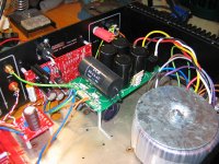
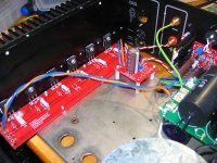
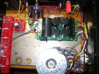
Here are some photos. If my chum doesn't come through with the other chassis then I'll have to transfer the whole thing. At the moment I have 250mV across the source resistors and the heatsinks are barely warm after 15 minutes.
Regards,
Chris
I'll measure that anyway.
Here are some photos. If my chum doesn't come through with the other chassis then I'll have to transfer the whole thing. At the moment I have 250mV across the source resistors and the heatsinks are barely warm after 15 minutes.
Regards,
Chris
Attachments
Let it run for 4 hrs like this and see where it goes. If it can take it, double the bias, or order another set of outputs!
Nice work!
Nice work!
I've pushed the bias up to 400mV and the heatsink temperature is rising to comfortable heat, however, the ambient temp in my workshop is about 12 deg C so I'm it's going to be running hotter in the house.
Regards,
Chris
Regards,
Chris
Hi friends
A simple question:
You can make a power supply to a BA2 +40-0-40 V?
can be dangerous?
I have at home a pair of transformers 28 0 28 AC,,,,,
any input?
rgds
A simple question:
You can make a power supply to a BA2 +40-0-40 V?
can be dangerous?
I have at home a pair of transformers 28 0 28 AC,,,,,
any input?
rgds
Not with the default input boards....There is a cascoded design Jim M made, that uses this, although he is using around a 36-40v tranny. I am using the same boards and tranny range.
Any reason not to use 47K resistor instead of 47.5K on BA-2 front end at resistors R203 and R204?
A wide range of value is OK. The false precision of 47.5K
is simply the result of using my favorite resistor type.
😎
Strange question to ask but how loud should the amp be? I've turned the pre-amp volume control to 3/4 of the way round and I'm just getting a reasonable output. The exposure amp on the other channel is too loud to listen to. Heatsinks are warm to hot at 410mV across the output resistors. Nice sound when I can hear it though! Running it in single-ended mode.
Any thoughts?
Regards,
Chris
Any thoughts?
Regards,
Chris
Last edited:
- Home
- Amplifiers
- Pass Labs
- Burning Amplifier BA-2