Well, here's this GE 5670 and the only thing I actually know about it is that its definitely awful in a circuit not designed for it.
I have need of a buffer, a preamp with a gain of about 6, or a phase splitter.
Currently, the project that I'm working on does happen to need a phase splitter. Its triple parallel LM1875 with hybrid variable current drive and capacitive multiplier power. Auto bridge is no good, DRV134 is not great, transformers are spendy, but here's this cute little tube. . .
However, I'd like to use the tube for what its best at and in a circuit designed for it, not a circuit designed for a near equivalent. Help?
Start with the data sheet. That's a GOOD looking twin triode. Its amplification factor (μ) is too large for your preamp application. However, its high transconductance of 5.5 mA./V. indicates service as either a cathode follower (buffer) or "concertina" phase splitter will be highly satisfactory.
GE's data sheet uses the absolute maximum rating system. Tubes operated under such conditions have short service lives. Back off 15% and get years of service out of the "bottle".
GE's data sheet uses the absolute maximum rating system. Tubes operated under such conditions have short service lives. Back off 15% and get years of service out of the "bottle".
So, is there some sort of cathode follower or concertina circuit that's optimal for GE 5670?
Well, a start would be getting it powered. Can it operate on 53vdc or should it have more?
Well, a start would be getting it powered. Can it operate on 53vdc or should it have more?
Well, it will draw current (e.g. at a grid bias of 0V), but it really depends on what you're trying to drive if this will be a good operating point. What sort of amplifier are we talking about here? If you're designing a phase splitter, what does the power stage look like? 2x EL84/6BQ5 or something? Or two triodes? Or a bunch of triodes running OTL?
Designing an audio circuit is essentially an optimization task. That means you need at least two things:
1. A goal or target - what are you trying to achieve
2. Awareness of other relevant variables; this includes the investments you're prepared to make, any stuff you have lying around, the time and skills you have, etc.
Can you be a bit more specific on the above?
So, is there some sort of cathode follower or concertina circuit that's optimal for GE 5670?
Well, a start would be getting it powered. Can it operate on 53vdc or should it have more?
A 53 VDC rail is way too "short". Look at page 5 of the data sheet, with its plate characteristics graph. A plate current of 9 mA. or so and a rail voltage around 160 V. looks good to me. Please notice that those numbers comport WELL with the data sheet's "typical" 8.2 mA. and 150 V. Allied Electronics own $16.35 6K1VF power trafo will take care of energizing the tube quite well.
Well, it will draw current (e.g. at a grid bias of 0V), but it really depends on what you're trying to drive if this will be a good operating point. What sort of amplifier are we talking about here? If you're designing a phase splitter, what does the power stage look like? 2x EL84/6BQ5 or something? Or two triodes? Or a bunch of triodes running OTL?
Designing an audio circuit is essentially an optimization task. That means you need at least two things:
1. A goal or target - what are you trying to achieve
2. Awareness of other relevant variables; this includes the investments you're prepared to make, any stuff you have lying around, the time and skills you have, etc.
Can you be a bit more specific on the above?
Yes, I'm not capable of designing a circuit for this tube, so I was hoping to find a circuit already optimized for GE 5670.
My amplifier input load is 100k.
A wide random selection of computer sound cards will have pretty treble with insufficient bass when driving ordinary transistors with 100k input load, or, at 10k there's dull treble, dull dynamics and a lot of bass. At every point in-between there yet more varieties of insufficient.
But, the problems are Less likely to occur when the "wide random selection of computer sound cards" drives a fet or tube.
When driving a tube, there's the opportunity for a "fresh" sound which is very helpful to the dull MP4 type codecs, such as AAC, Itunes, and HD radio. This "fresh" (not quite brash) sound exhibited by the harmonics of some tube buffers, saves the day for many computer sources and isn't particularly harmful to other sources. At about that point, you come up with a reason to use an amplifier on a computer source.
This description seems to call for a triode; however, maybe not the GE 5670. Due to the absence of designs specifically for that model tube, creating support circuitry for it seems like a wasteful shot in the dark. Searches for uses for it come up somewhere between indecipherable and nil, so by going on popularity alone, I'd have to believe that my little tube needs to stay in its box.
Thanks for your time.
hey daniel - your op is as odd as stating "i have a MJE350 what's a great circuit for it?"
Having said that, put it up front of your LM amp and it may be a visual (although not necessarily sonic) addition.
Having said that, put it up front of your LM amp and it may be a visual (although not necessarily sonic) addition.
Well, I would like to know what tube buffer (and known-good applied circuit) would indeed make the sonic inflection as described above in post #6, and working correctly at dc voltage between 57 and 70?hey daniel - your op is as odd as stating "i have a MJE350 what's a great circuit for it?"
Having said that, put it up front of your LM amp and it may be a visual (although not necessarily sonic) addition.
A great circuit for MJE350? Are you reading my mind?
This is funny because I was searching through my parts box to find transistors with a High Voltage rating to make capacitive multiplier for this project and found MJE15032, MJE15033 pairs. . . as if BD139, BD140 that could run on much higher voltage. I can't really read/interpret the particulars on the MJE15033, MJE15032 datasheet(s), but it looks and smells workable. 🙂
While searching, I did manage to find a production circuit that actually uses GE 5760 tube.
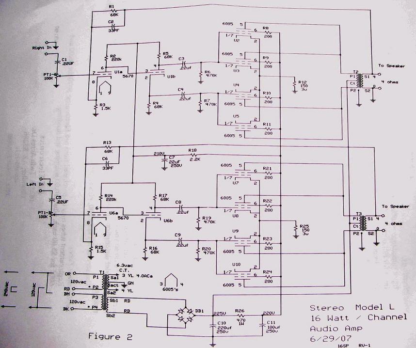
Yes, the negative feedback is there to reduce distortion and to flatten the frequency response. However, I take it you will only be using the input stage and phase splitter portion of this circuit. I assume that the LM1875 accepts line level inputs. This would mean that using a concertina phase splitter (i.e. one 5670 half per channel) would be ok, since you don't need over-unity gain. You could decide to buffer the input with the other half of the tube (then you'll need 2 5670's for stereo) as is done here, but you won't need much gain. Less than in the schematic you posted above.
I don't think there's a ready-made and optimized schematic for your particular application. The topology of the 16LS kit (which I assume that is) you refer to will certainly work, but it might (will) need optimization for your particular purpose, since driving a PP (double) pair of 6005's is different from driving an LM1875.
I don't think there's a ready-made and optimized schematic for your particular application. The topology of the 16LS kit (which I assume that is) you refer to will certainly work, but it might (will) need optimization for your particular purpose, since driving a PP (double) pair of 6005's is different from driving an LM1875.
5670 driving pp EL84
See if schematic in this thread helps - measured voltages are indicated (thanks to Svein B.)
It is actually a very good sounding tube.
http://www.diyaudio.com/forums/tubes-valves/81556-yarland-34-ciii-amp.html
See if schematic in this thread helps - measured voltages are indicated (thanks to Svein B.)
It is actually a very good sounding tube.
http://www.diyaudio.com/forums/tubes-valves/81556-yarland-34-ciii-amp.html
Yes, the negative feedback is there to reduce distortion and to flatten the frequency response. However, I take it you will only be using the input stage and phase splitter portion of this circuit. I assume that the LM1875 accepts line level inputs. This would mean that using a concertina phase splitter (i.e. one 5670 half per channel) would be ok, since you don't need over-unity gain. You could decide to buffer the input with the other half of the tube (then you'll need 2 5670's for stereo) as is done here, but you won't need much gain. Less than in the schematic you posted above.
I don't think there's a ready-made and optimized schematic for your particular application. The topology of the 16LS kit (which I assume that is) you refer to will certainly work, but it might (will) need optimization for your particular purpose, since driving a PP (double) pair of 6005's is different from driving an LM1875.
Okay, how to re-configure the tube circuit to drive 100k instead of 470k?
These are triple parallel LM1875 amplifiers with 100k input load (not line level).
It would be most interesting to create 1 concertina (for bridge amp), 1 buffer, and 1 combination.
P.S. The power would be much less expensive if it was okay to run the tube on 100vdc. All of my parts would work. 🙂
Dan,
You might be able to get a 6922 to work for you at 70 V.
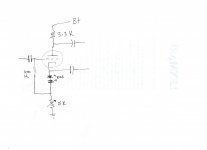
I think you can achieve that which appears to be your objective, using the 5670. It seems you want circuitry that adds a small amount of 2nd harmonic distortion to the "harsh", digitally generated, I/P signal. It is common to use at least 3X the triode's plate resistance as the net load impedance, as this makes for linearity. Use a lesser load and HD goes up, which is what your application needs. 😉
I've attached a crude schematic of a setup which serves as both I/P buffer and phase splitter. The 5 KOhm variable resistor is adjusted to make the pair of 180o out of phase signals otherwise "identical". You will need the "160" V. supply I mentioned previously.
You might be able to get a 6922 to work for you at 70 V.
I think you can achieve that which appears to be your objective, using the 5670. It seems you want circuitry that adds a small amount of 2nd harmonic distortion to the "harsh", digitally generated, I/P signal. It is common to use at least 3X the triode's plate resistance as the net load impedance, as this makes for linearity. Use a lesser load and HD goes up, which is what your application needs. 😉
I've attached a crude schematic of a setup which serves as both I/P buffer and phase splitter. The 5 KOhm variable resistor is adjusted to make the pair of 180o out of phase signals otherwise "identical". You will need the "160" V. supply I mentioned previously.
Attachments
Last edited:
It seems you want circuitry that adds a small amount of 2nd harmonic distortion to the "harsh", digitally generated, I/P signal. It is common to use at least 3X the triode's plate resistance as the net load impedance, as this makes for linearity. Use a lesser load and HD goes up, which is what your application needs. 😉
Thank you for the drawing! Its very simple and do-able. Those LED's--clear, but shines with a wine red light? Is there a specific model or range of tolerances / specifications to look for?
To put it bluntly, many of the codecs, especially MP4 types are dull at the voice band and with treble harmonics that's slightly shouty and otherwise missing. So, the needed effect is "fresh" as in "nearly brash," but Not actually raspy. And yes, it would be wonderful if the amount of effect was adjustable.
Caveat: Most computer sound cards do well with approximately 11k load, else the extra low bass notes may be absent. I don't know why.
Pick LEDs that can comfortably handle the 9 or so mA. of current present. Off the top of my head, I don't know what size ("regular" or jumbo) to use.
You can tweak the grid to ground resistance, but a lower value requires the I/P cap. value to increase. That RC combo is a high pass filter. Speaking of the I/P cap., use a Soviet surplus paper in oil (PIO) part there for smoothness.
An important feature I left out of the drawing is a grid stopper resistor. Install a 1 KOhm Carbon composition (CC) part, with its body as close to the grid connection socket lug as can be. Use the "free" end of stopper as the connection point for the I/P cap. and grid to ground resistor. High transconductance (gm) types are vulnerable to parasitic oscillation. The stopper resistor is installed to block that nastiness.
Speaking of the I/P cap., use a Soviet surplus paper in oil (PIO) part there for smoothness.
Very much unlike the CD player source: With a computer source, you don't want to hold back any part of the audio band at the amplifier's input. With computer source, its like a "tug of war" and so a critically clean cap choice is needed for input.
Examples:
I don't want raspy, but do need a harmonic extrapolation.
I don't want shouty, but do need clarity.
However: If the smoothness is needed because of the tube, then the oil cap would be the tube's output cap.
Any standard (i.e. cheap) 5mm led will do; those are usually rated for 20mA, and light up pretty much completely at half that current. So as a nice bonus, you get some red light.Pick LEDs that can comfortably handle the 9 or so mA. of current present. Off the top of my head, I don't know what size ("regular" or jumbo) to use.
Note that in the schematic Eli posted, the 5k variable resistor is not used to dial in more or less distortion; it is used to adjust the balance between the in-phase and out-of-phase output signals. Which, incidentally, one could also interpret as a means to introduce (or prevent) distortion, so it might be what you're looking for. The HD Eli refers to is caused by choosing a relatively low value for the anode resistor (the 3.3k one). Of course, you could consider experimenting with that value as well for the most enjoyable amount of distortion.And yes, it would be wonderful if the amount of effect was adjustable.
I won't be going into the subjective qualifications ('smooth', 'clarity', 'shouty'), because I don't know what they mean in terms of electronics and circuit behavior. On top of that, they probably mean different things to different people, which is inherent to anything subjective. Nevertheless, introducing some 2nd harmonic distortion is usually experienced by people as a nice 'warming up of the tone'. That's about as far as I can venture into the audio-equivalents of wine tasting comments (which I don't understand either) 😉
Weird Question: Is reverse splitter possible, as a mixer for realistic monophonic from stereo source without all the dull cancellations of typical resistor mixers?
If that's possible, then it can be used for the center channel amplifier in a trio format setup. Ever heard one? The sound field is amazing no matter which chair you sit in, the power is dramatic, and the dynamics are stunning. Its as if the stage reinforcement is present, rather than the boring effect of only the main. Its like you're on the stage, IN the music. Howabout that?
If that's possible, then it can be used for the center channel amplifier in a trio format setup. Ever heard one? The sound field is amazing no matter which chair you sit in, the power is dramatic, and the dynamics are stunning. Its as if the stage reinforcement is present, rather than the boring effect of only the main. Its like you're on the stage, IN the music. Howabout that?
Dan,
Mastodon's remarks are spot on.
Film dielectric caps. are frequently called "bright". That's why I suggested PIO at the I/P. If transparency is to your liking, use polystyrene film and foil in those positions.
BTW, a cost effective and good sounding option for the O/P coupling positions is metalized polypropylene bypassed by polypropylene film and foil. A 4.7 μF. primary part and a 0.47 μF. bypass works well into the IHF 10 KOhm "standard". Lower values work into higher I/P impedances. Yes, we're dealing with yet another high pass pole and a F3 <= 5 Hz. is in order.
I won't be going into the subjective qualifications ('smooth', 'clarity', 'shouty'), because I don't know what they mean in terms of electronics and circuit behavior.
Example:
Exactly the needed harmonic effect to correct MP4 (HD radio, Itunes, Movies, Transcodes) would be provided by a Chinese 6n3 current follower on slightly insufficient voltage (typical use), whereby at near limitation it provides useful harmonic extrapolation. This current follower is at the input to a solid state bridge symmetry amplifier with far too much gain so that the power amp makes dynamic expansion. The tube should enter clipping with helpful limiting before the solid state power amp could start to clip. Both stages are clarified (higher resolution) by running from capacitive multipliers.
This example has the desired harmonic effect (somewhat brash tube fixes dull mp4); but, unfortunately the amplitude of the effect is too great.
With that "overkill" problem, the example above serves only to exchange one sort of noise in trade for a slightly better quality noise. It is stunningly effective and problematically overly effective. 🙂
Theoretically, the amplitude of the effect an be adjusted (increased or decreased) by balancing the power supply voltage of the tube buffer versus the gain of the power amp.
But that is beyond the scope of my experience, as my efforts with tubes were either combination of "far too much of a good thing" -OR- completely at the wrong pitch, as in too low-pitched to remedy the damaged treble harmonics of Mp4 and similar problem sources.
Purpose:
This amplifier arrangement is for live time post processing to repair a signal that was damaged during recording. Most computer sound cards and digital effects are incapable of this type of post processing and cannot provide playback that is reasonably comparable to a live experience when amplified. . . unless the audio amplifier has inbuilt extrapolation as an extension of its basic function.
The needed amplifier device is first cousin to a quality hybrid guitar amplifier.
With its inbuilt effect, it cannot belong to the hi-fi classification; but, you can consider it an extraordinary mid-fi designed be pleasant at high output, despite using a computer as a source. That seems useful.
P.S.
I'll try to come up with some schematic example for the 6n3 tube as used in the example above. However, the frequency at which is harmonic output is strongest occurs at a higher (and more useful) frequency than GE 5670. They're apparently not very related, despite same pinout.
I don't know how to relocate this frequency with a tube.
With non-inverting LM1875, you simply use higher figures for feedback resistor for more treble (up to almost 133k) and then proceed to compensate the rest of the design.
How is that sort of thing done with a triode?
- Status
- Not open for further replies.
- Home
- Amplifiers
- Tubes / Valves
- toob noob with GE 5670 and I'd like to do something with it. Help?