It is important to combine purchases, when possible. Otherwise, shipping charges can eat you alive. Since the power trafo comes from Allied Electronics, it makes sense to order the CLC filter's inductor from them too. $7.93 buys stock # 967-1009 which is a 10 H./50 mA. Triad C-3X.
Contact Jim McShane about 'lytics for the project. Jim may be able to help with other parts, including the 600 PIV Schottky diodes, too. Point the man at this thread. Jim's shipping charge policy is favorable and his prices are otherwise quite fair.
Okay, I've send Jim an E-mail.
P.S.
In order to help the point, that I'd like to use the tube to "put in" the brash sound of CD into the dull MP4, I'd like to use Elna Cerafine caps//polyester wherever suitable. Suggestions for other nice crisply clear parts are very welcome.
You can't put back that which nasty compression algorithms have discarded. However, a certain amount of 2nd harmonic distortion added to the signal will make it sound more "musical".
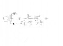
Let's review what you need for the full wave center tapped (FWCT) B+ supply. You already have Allied stock #s for magnetics. You need a pair of 600 PIV Schottky diodes. You need 2X 250 WVDC filter capacitors. IIRC from conversations with McShane, he stocks 330 μF. parts of good quality. A couple of those in combination with the C-3X choke will knock the residual ripple level WAY down and keep the rail voltage up. However, such a large capacitance at the filter's I/P is not without issues. To prevent power trafo clanging at turn on, install a CL90 inrush current limiter between the junction of the 2 Schottky cathodes and the PSU filter. In addition, Fourier's theorem tells us that the highly "triangular" ripple waveform associated with a large I/P cap. contains ripple fundamental overtones extending well into RF. That "hash" can get past the filter choke due to the capacitance of the many close spaced turns of wire. You deal with that most unwelcome trash by inserting a LC section made of a RF choke and a 1000 pF. mica or NPO ceramic cap. between the 1st filter cap. and the C-3X. McShane has suitable parts for the "hash" filter.
Highly transparent polystyrene and polypropylene signal caps. were mentioned earlier and I'll stick with that advice.
Thank you very much!
There's a slight problem--I actually read that through about four times, but can't quite get it in my head, and therefore, can't build it. May I have a sketch of the power circuit or is there an example schematic that's very similar?
There's a slight problem--I actually read that through about four times, but can't quite get it in my head, and therefore, can't build it. May I have a sketch of the power circuit or is there an example schematic that's very similar?
Look here for a description of a FWCT setup. The CL90 inrush limiter is inserted between the junction of the 2 cathodes and the load (filter).
A Π (Pi) section, AKA CLC, filter is, in fact, a cap. I/P filter followed by a LC section. I advised you insert a LC section made from RF parts between the I/P cap. and the "routine" LC section. Can you say "dead" quiet? 😀 Regulation is pretty darn good too, given the heft (330 μF.) of the filter caps. being used.
A Π (Pi) section, AKA CLC, filter is, in fact, a cap. I/P filter followed by a LC section. I advised you insert a LC section made from RF parts between the I/P cap. and the "routine" LC section. Can you say "dead" quiet? 😀 Regulation is pretty darn good too, given the heft (330 μF.) of the filter caps. being used.
Oh dear. I'm sorry but I didn't get any sort of clear picture on how to build what's described. PI filter (typically, cap, resistor, cap just like a guitar amp supply should be) followed by LC filter. . . this, in addition to the rail splitter clues is telling me that the number of high voltage 330uF caps to buy may be 6 (three per rail).
Is that true?
Really, this is like a sack race in pitch dark.
This is embarrassing! Usually my imagination can come up with a good power supply, but I'm having absolutely no luck envisioning this power supply. Again, I'm sorry, but I'm "stuck" for lack of a sketch. Um? Please turn on the lights? 🙂
Is that true?
Really, this is like a sack race in pitch dark.
This is embarrassing! Usually my imagination can come up with a good power supply, but I'm having absolutely no luck envisioning this power supply. Again, I'm sorry, but I'm "stuck" for lack of a sketch. Um? Please turn on the lights? 🙂
Oh, thank you! That makes sense!
I had made a sketch from the narratives, got the smaller inductor and the smallest cap in the wrong place.
Ah, now there's something about a voltage divider and a virtual center tap on B+ and a virtual center tap on heater and a link between both virtual center taps? Is that right?
Well, I imagined that maybe the B+ just used a pair of 22k resistors, while the heater used the 5R that you mentioned earlier. Is that right?
So, I didn't know where the voltage divider went unless that happens to refer to the virtual center tap simply dividing by half. So, is there additional voltage dividers?
- Status
- Not open for further replies.
- Home
- Amplifiers
- Tubes / Valves
- toob noob with GE 5670 and I'd like to do something with it. Help?