Im also going to make the F5. Got pcb and some of the parts.
Have looked in this thread but im not sure how big the heatsinks should be.
Bias i think should just be standard.
I see 2 options.
modu
or something from
HeatsinkUSA
Have looked in this thread but im not sure how big the heatsinks should be.
Bias i think should just be standard.
I see 2 options.
modu
or something from
HeatsinkUSA
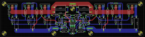
That looks nice! Have you noticed that psu board looks like a bomber plane?
Btw you might think about have optional off-set legs on the trimpots - most I have bought came with middle leg not in line with the rest.

Buying trimpots form farnell, they have the correct version with in line legs. 🙂
5U, 400mm
500mm heatsinks appears to be made of two each side, and not so good
400mm looks like one piece each side, and much better
hmm, with raised power, wouldnt you need stronger source and feedback resistors ?
Hmm, maybe?
Havent really thought about that.
😕
5U, 400mm
500mm heatsinks appears to be made of two each side, and not so good
400mm looks like one piece each side, and much better
Thanks. 🙂
Think I finally found a configuration I am happy with.
CRC PSU 3 x 18,000 uF - 4 x 1R0 - 4 x 18,000 uF, one for each channel
I almost win. 😀
http://www.diyaudio.com/forums/pass-labs/121228-f5-power-amplifier-988.html#post2432118
hmm, with raised power, wouldnt you need stronger source and feedback resistors ?
Wise!
I forgot that too.
Hmm, should one change from fast on connector to a through-hole mounting pad instead?
Fast on is easy to work with but the most optimal solution would be to solder wires to the PSU and Amp PCB.
Regarding feedback and source resistors with higher power levels, what would a reasonable size be?
Fast on is easy to work with but the most optimal solution would be to solder wires to the PSU and Amp PCB.
Regarding feedback and source resistors with higher power levels, what would a reasonable size be?
Last edited:
hmm, with raised power, wouldnt you need stronger source and feedback resistors ?
If you're going to be pumping continuous waves at full
power you probably will. Panasonic makes 5 watt versions
of the same resistors.
😎
What resistors are we talking about exactly? The source resistors the JFETs and the 4 x feedback resistors?
What resistors are we talking about exactly? The source resistors the JFETs and the 4 x feedback resistors?
source power outputs, from supply
and feedback to Jfets, from output
source power outputs, from supply
and feedback to Jfets, from output
Offcourse, dont know what I was thinking. 😕
Hmm, hope I have room for 5 watt resistors. Better do a small redesign. 🙂
Input jfets source resistors. (feedback current to ground)
As there are three outputs, current is divided into the three source resistors.
As there are three outputs, current is divided into the three source resistors.
Last edited:
Input jfets source resistors. (feedback current to ground)
As there are three outputs, current is divided
I dont think the JFET source resistors are a problem.
The jfet source resistors and feedback resistors form dividers. They share the same current.
Or, if you prefer, the same current flows through both.
Or, if you prefer, the same current flows through both.
Last edited:
The jfet source resistor and feedback resistors form a divider. They share the same current.
Or, if you prefer, the same current flows through both.
Yes, but the voltage drop across them is alot smaller than the 4 100 Ohm resistors.
Yes, but the voltage drop across them is alot smaller than the 4 100 Ohm resistors.
JFET source resistors, increasing them to 2 watts, would be ok I think.
- Home
- Amplifiers
- Pass Labs
- F5 power amplifier