Well, it probably is, but the stock F5 has 30mF. For class A operation, it doesn't matter, but I'm thinking mostly about the class B peaks. Do you have 4 or 8 ohm speakers?
8 ohm nominal speakers but they dip to 4 ohm in the bass region. Would theoretically need about 8,4 A with a 4 ohm load and 37 volts supply voltage.
for ClassA it does matter. The supply rails will vary in current demand from 0.002Amperes to 2.598Amperes when driving 27W into an 8r0 resistive load.Well, it probably is, but the stock F5 has 30mF. For class A operation, it doesn't matter,
Oh, we still have to account for the current flowing in the NFB loop.
What is predicted for the ripple voltage on that final 15400uF when the current rises to 2.6Aperes?
Would one expect the ripple voltage to be halved when the smoothing capacitance is doubled?
This does not consider the peak transient currents that real speakers will demand from the supply rails. 4ohms speakers will make this case even more difficult to satisfy.
How can you expect the amplifier to do it's job well if the PSU cannot meet expected current demand?
Last edited:
When you have an output of 4,6 A RMS the ripple voltage on the 3rd C will be 66mV with a current of 228mA in the 3rd C. The load on the 3rd C is very low, the 1st C does most of the work.
But thats with my high power F5 with 37 volt rails and full power into an 8 ohm load.
But thats with my high power F5 with 37 volt rails and full power into an 8 ohm load.
Probably not. I glue mine right to the case of the Mosfet,
which minimizes the open case effect.
😎
I thought the "open case effect" was my imagination. I'd like to try this, what type of glue is used for this fairly high heat application?
Russellc
Araldite. (Two components resin.)
Thanks, I'll google that one and seek it out. Thanks again!
Russellc
RTV Silicone ( that red goo) is more than good enough
just one tiny blob - to keep NTC in close contact with heatsink
don't put any glue in between NTC body and heatsink , just side vise
just one tiny blob - to keep NTC in close contact with heatsink
don't put any glue in between NTC body and heatsink , just side vise
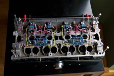
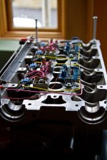
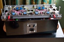
Here are the pics I promised earlier in the thread.
I have a problem though...... something is going on with Q4 when I connect up the speaker (just one channel, left side in the pics) for some reason when I connect the speaker the 0.47R resistor for Q4 smokes. It does this whether the inputs are shorted or not.
Could this be oscillation? I did use a gate stopper - its on the board, (PDs F5 boards) but I haven't seen anyone else report problems even though it could be mounted right on the leg.
Fran
Attachments
an inspiration to see something different, nice
your transistor mounting screws are not fully in ?
your transistor mounting screws are not fully in ?
No, they're in fully - well tightened down.
I went back and added in the temp compensation stuff - thing is, when I tried back out in my workshop, it all powered up fine. I had these hooked up to my stacked quads when the resistor smoked. I wonder if thats something to do with it. They would present a pretty bad load. No problems when hooked up to the test speakers.
I'm doing some more investigating.... can't see anything wrong in my wiring etc....
Fran
Here are the pics I promised earlier in the thread.
I have a problem though...... something is going on with Q4 when I connect up the speaker (just one channel, left side in the pics) for some reason when I connect the speaker the 0.47R resistor for Q4 smokes. It does this whether the inputs are shorted or not.
Could this be oscillation? I did use a gate stopper - its on the board, (PDs F5 boards) but I haven't seen anyone else report problems even though it could be mounted right on the leg.
Fran
Nice... a high rewing 16V - F5 !
Did you check the isolation for the MosFet?
Arne K
No, they're in fully - well tightened down.
I went back and added in the temp compensation stuff - thing is, when I tried back out in my workshop, it all powered up fine. I had these hooked up to my stacked quads when the resistor smoked. I wonder if thats something to do with it. They would present a pretty bad load. No problems when hooked up to the test speakers.
I'm doing some more investigating.... can't see anything wrong in my wiring etc....
Fran
From the manual!
"A caveat is in order here – this is a very wide band amplifier with a high input
impedance. In order to prevent the output voltage from bleeding back to the
input at very high frequencies (thus making a fine power oscillator), keep the
input and output cables separate, and don’t externally connect the speaker
ground to the input ground. Good ground shielding on the input cables is
important, and caution is called for in using Litz and other specially low
inductance / high capacitance cables. I have not seen a specific example of a
problem, but historically it is to be expected when an amplifier’s bandwidth
exceeds 200 KHz. If the amp makes funny noises, runs extra hot, or blows
fuses, this might be an indicator of such an issue."
Your pictures missing rca ground!!!!
No, RCA ground is there alright - its kinda tucked around the RCA jack and runs along the piece of alu angle to the star ground on each PS.
The amp plays perfectly with my horns.... so I'm starting to think that this may be an issue with the other speakers I hooked it up to.... stacked quads. I reckon it doesn't like the impedance presented by them.
Anyway, I haven;t actually made up my mind on this..... need more time. I was blaming my valve pre but now I don't think it was the issue.
Fran
Ooh! Finally photos of the cylinder head amp! It looks great!
Hopefully you get it tuned up and working properly soon.
Hopefully you get it tuned up and working properly soon.
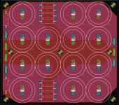
Think I finally found a configuration I am happy with.
CRC PSU 3 x 18,000 uF - 4 x 1R0 - 4 x 18,000 uF, one for each channel
F5 cascoded input with 3 x output pairs.
38 Volts supply, around 70W/8 ohm.
🙂
Now I just need to get PCBs made, unless I have a few last minute changes.
CRC PSU 3 x 18,000 uF - 4 x 1R0 - 4 x 18,000 uF, one for each channel
F5 cascoded input with 3 x output pairs.
38 Volts supply, around 70W/8 ohm.
🙂
Now I just need to get PCBs made, unless I have a few last minute changes.
Attachments
- Home
- Amplifiers
- Pass Labs
- F5 power amplifier


