Hi,Can I use VI Limiter like in quasi complementary BJT amp or doesnt work to protect Mosfets ?
If not how can I protect Mosfets in this amp Short circuit condition, can you draw small schematic ?
regards
use a Zener across the gate to source or gate to output of the final stage.
Instead of using a 12V Zener and a diode allowing upto 12.7V and in turn allowing enormous current to pass through the output device.
Reduce the Zener to 6V. Now look up the Id vs Vgs plot and see how much current the FET passes when Vds is high.
If 6.7V is a bit too low on Id then try 7V or 8V or etc.
This is quite effective current limit.
The Zener can be tapped into the top or bottom of the source resistor. The protection locus for these two locations are different, Investigate and choose the characteristic you prefer.
Because the Zener protection is so effective, many designers and builders say that IV protection is unnecessary. You evaluate.
Now Back to the Zener. When it protects it pulls current from the driver to the output line. Effectively the driver is now trying to drive the fault load through the Zener bypassing the output FET.
You must design the driver and the gate stopper and the preceding stage to survive this fault operation.
A current limiter on the VAS or the pre-driver may be required.
Last edited:
Do you recommend a separate zener for each fet one one for all on upper side and one for all on lower side ?
Hi,
use a Zener across the gate to source or gate to output of the final stage.
Instead of using a 12V Zener and a diode allowing upto 12.7V and in turn allowing enormous current to pass through the output device.
Reduce the Zener to 6V. Now look up the Id vs Vgs plot and see how much current the FET passes when Vds is high.
If 6.7V is a bit too low on Id then try 7V or 8V or etc.
This is quite effective current limit.
The Zener can be tapped into the top or bottom of the source resistor. The protection locus for these two locations are different, Investigate and choose the characteristic you prefer.
Because the Zener protection is so effective, many designers and builders say that IV protection is unnecessary. You evaluate.
Now Back to the Zener. When it protects it pulls current from the driver to the output line. Effectively the driver is now trying to drive the fault load through the Zener bypassing the output FET.
You must design the driver and the gate stopper and the preceding stage to survive this fault operation.
A current limiter on the VAS or the pre-driver may be required.
Andrew what you said is VALID only in case of Lateral Mosfets not with Vertical Mosfets.
Laterals have low Transconductance than Verticals, Zener limiting is of NO use other than protecting Gate from Transients induced from miller charge.
Take a look at datasheet of IRFP460 Id Vs VGS Graph,
AT 6V VGS it is happily conducting more than 20Amperes,
How in real world you will say it could limit the current well within in SOA and safeguard against Blow up?????😕
Can I use VI Limiter like in quasi complementary BJT amp or doesnt work to protect Mosfets ?
If not how can I protect Mosfets in this amp Short circuit condition, can you draw small schematic ?
regards
No you cannot use that VI limiter thing to protect your mosfets from Short Circuit.
To Protect Vertical Mosfets you need a dedicated separate driver stage and fast acting shutdown latching mechanism.
You have quoted from a particular datasheet to undermine the argument.Take a look at datasheet of IRFP460 Id Vs VGS Graph,
AT 6V VGS it is happily conducting more than 20Amperes,
Instead what you could do is select a Vgs that would fit with providing a short term current limit in event of an output short.
That would have been much more useful to the questioner and would also have not left him wondering which of us is talking through a hole in our hat.
Have you considered the case where the Zener is tapped into the output line?
I suspect not even though I gave clear guidance that this produced a different locus and should be evaluated.
Note, my advice was for the general case and allowed the builder to design his short circuit protection to suit his/her chosen device.
Your response did not try to help.
If there is a part of my development that is in error, or simply wrong, then elaborate, do throw out the whole argument.
I just looked up the irf460 datasheet. At cold it will pass ~37Apk when Vgs is limited to 6V.
The SOA says that cold, the device will pass 37Apk for very approximately 3ms.
What's the problem? As said above what specifically is wrong with the way I suggested investigating the level of short circuit current limit and what is wrong with selecting an appropriate maximum Vgs to limit the risk of output stage damage, or maybe none at all.
Try 5.5Vgs limit or 5Vgs limit and evaluate.
The builder or you can refer to the irfp460 datasheet.
Last edited:
You have quoted from a particular datasheet to undermine the argument.
Instead what you could do is select a Vgs that would fit with providing a short term current limit in event of an output short.
That would have been much more useful to the questioner and would also have not left him wondering which of us is talking through a hole in our hat.
Have you considered the case where the Zener is tapped into the output line?
I suspect not even though I gave clear guidance that this produced a different locus and should be evaluated.
Note, my advice was for the general case and allowed the builder to design his short circuit protection to suit his/her chosen device.
Your response did not try to help.
If there is a part of my development that is in error, or simply wrong, then elaborate, do throw out the whole argument.
I just looked up the irf460 datasheet. At cold it will pass ~37Apk when Vgs is limited to 6V.
The SOA says that cold, the device will pass 37Apk for very approximately 3ms.
What's the problem? As said above what specifically is wrong with the way I suggested investigating the level of short circuit current limit and what is wrong with selecting an appropriate maximum Vgs to limit the risk of output stage damage, or maybe none at all.
Try 5.5Vgs limit or 5Vgs limit and evaluate.
The builder or you can refer to the irfp460 datasheet.
Don't Escape when you fall short on your own previous arguments.
You cannot Safeguard a Vertical FET with a 5V Zener also.
The reason i quoted the IRF460 because Quasi's amplifier uses this particular FET and also used by many members here in this thread, Got that.
In Case of Vertical Mosfets specially from IR and APT
Zener has no role in protecting the amplifier during short circuits, keep this in mind. Zener only helps in protecting gate damage from transients.
A short term current limit of upto 10 or 37A with time period of 3mS is of no worth.
I have simply stated the facts by calling a spade a spade and a reasoning with valid statements.
Last edited:
this reply more than suggests there is no worth in the provision of short circuit protection by Zener limiting the Vgs that can be applied to the output FET.
I cannot recall your valid statements that support your contention that Zeners only protect the gates from excessive Vgs.
I do wish you would take the time to explain to me in particular and the other Members looking for simple and cheap protection schemes.I have simply stated the facts by calling a spade a spade and a reasoning with valid statements.
I cannot recall your valid statements that support your contention that Zeners only protect the gates from excessive Vgs.
Last edited:
this reply more than suggests there is no worth in the provision of short circuit protection by Zener limiting the Vgs that can be applied to the output FET.
I do wish you would take the time to explain to me in particular and the other Members looking for simple and cheap protection schemes.
Yes there is no worth by implementing Zener for protection of shortcircuit in the case of Vertical mosfets.
To Safeguard mosfet in event of short circuit the only valid solution is to turn off the gate drive and let the mosfet to turn off in slow manner[provided their is a passive resistor say 1k connected between G-S of mosfet]
In Event of short circuit following thing happens:
Id rises sharply which inturn gives rise to high di/dt
Transient on DS appears so rapidly if not controlled leds to avalanche.
Now if you clamp the mosfet with say regular VI limiter, it will clamp the G to S terminal causing the mosfet to switch-off rapidly, good in theory but in pratical it causes another failure mode due to High Id conducting thru mosfet in case of short circuit, the Gate fails instantly due to extreme di/dt and mosfet smokes. Miller charge on D-G of mosfets rises abnormally during short circuit conditions which exceeds maximum aloowable 30V VGS rating that why zener is good for transient protection of gate, only valid approach is to let the turn off as passive and take the gate drive immediately upon sensing the short circuit.
Last edited:
I have downloaded the correct irfp460 datasheet.
at 5Vgs it passes ~ 23Apk
The SOA shows that this device can pass 23Apk for very approximately 50ms.
What's wrong with that?
A pair of devices could be set to a total maximum short circuit current limit of ~40A. How long will the rail fuses last?
Now move the Zener tapping to the bottom side of the source resistor, i.e. to the output. One can take advantage of the Vdrop through the source resistor to put a slope in the current limit locus.
||I cannot recall your valid statements that support your contention that Zeners only protect the gates from excessive Vgs.
\/
Zener only helps in protecting gate damage from transients.
that is a much better approach. A well reasoned argument that shows why I am wrong.Now if you clamp the mosfet with say regular VI limiter, it will clamp the G to S terminal causing the mosfet to switch-off rapidly, good in theory but in pratical it causes another failure mode due to High Id conducting thru mosfet in case of short circuit, the Gate fails instantly due to extreme di/dt and mosfet smokes. Miller charge on D-G of mosfets rises abnormally during short circuit conditions which exceeds maximum aloowable 30V VGS rating that why zener is good for transient protection of gate, only valid approach is to let the turn off as passive and take the gate drive immediately upon sensing the short circuit.
I will need to go and do more homework.
Thanks for the pointers.
Last edited:
I have downloaded the correct irfp460 datasheet.
at 5Vgs it passes ~ 23Apk
The SOA shows that this device can pass 23Apk for very approximately 50ms.What's wrong with that?A pair of devices could be set to a total maximum short circuit current limit of ~40A. How long will the rail fuses last?
Now move the Zener tapping to the bottom side of the source resistor, i.e. to the output. One can take advantage of the Vdrop through the source resistor to put a slope in the current limit locus.
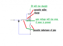
50mS is on datasheet for 23Apk...........agreed, but you fail to see what i just told in my post which explains in detail about the phenomena which happens during Short circuit.
You can limit the Gate with Zener of 5V say upto 23pk, but you cannot trap the parasitic miller charge building inthe mosfet between D G terminals which causes the rise of gate voltage even in the presence of 5v zener on gate to source or source resistor output pin, the parasitic voltage will built up so rapidly that it will exceed the Vz limit of zener alone because of FINITE INDUCTANCE OF PIN and this happens in NANOSECONDS and mosfets are bloody fast to react in such a short time interval.
Attachments
Last edited:
post89 was not there when I started downloading the other datasheet and looking at the graphs.
Post 92 acknowledged your informative post and thanked for the contribution.
Post 92 acknowledged your informative post and thanked for the contribution.
and what an we do no ? Zener should be better than nothings ?post89 was not there when I started downloading the other datasheet and looking at the graphs.
Post 92 acknowledged your informative post and thanked for the contribution.
hi quasi
greetings built your actrk 600 have biasing problems could not get
50 OHMS PRESET so took 100 OHMS PRESET AND PUT A 100 OHM RESISTANCE
PARALLEL TO PRESET WILL THIS WORK OUT
THANKING YOU
ANDREW LEBON
greetings built your actrk 600 have biasing problems could not get
50 OHMS PRESET so took 100 OHMS PRESET AND PUT A 100 OHM RESISTANCE
PARALLEL TO PRESET WILL THIS WORK OUT
THANKING YOU
ANDREW LEBON
Yes, very much, I'm just waiting for ID's next sign of life. 🙂Maybe we should return the thread to helping fix the amp in question?
Kanwar,
FETs should be driven by a voltage amplifier. My first consideration is signal transfer and I`m aware of the conflicting factors.
Hi,
at 30 mA bias current most parameters will be very poorly defined, would 100 mA per device be too much to ask? Except that I can only come up with placing ugly compensation capacitors in some position.
- Home
- Amplifiers
- Solid State
- NMOS 350/500 by Quasi