To paraphrase that great vacuum tube designer, Rene Magritte, "Ceci n'est-ce pas une amp."
Sorry - this SIMULATION is scary!!!
BTW, I traced a few of the curves of models of the 6AS7G as well as the 6SN7 and they are very accurate except when the tube approaches cutoff. The models cut off more abruptly than the real curves, but not enough to significantly affect the results of simulations where the object is to determine the output power the amp should be capable of.
The simulation isn't going to completely and accurately describe all the nuances of the behavior of the circuit, but anyone who thinks that simulation of vacuum tube circuits is in its infancy is wrong IMHO. PSPICE and other simulation tools can yeild very accurate results when properly used. Mine is a tale of "operator error". Mystery finally solved. PSPICE was not to blame nor were the models used for the inaccurate answers.
Last edited:
The output shows a slight asymetry which, since its balanced, must be due to the input its getting, but otherwise it looks pretty good.
An externally hosted image should be here but it was not working when we last tested it.
An externally hosted image should be here but it was not working when we last tested it.
The asymetry it turns out was due to the output being taken from the tube side of a 1 ohm cathode resistor instead of the load side. When that's corrected the output is a clean 400 watts+ RMS output. How "clean" it actually is seems to depend on signal level according to the FFT that PSPICE is capable of.
Sampleaccurate a you realy want to made 2x400W OTL?😱
Got some good DJ mixes musik if you want to made some realy loud party with this Amps🙂
Best Regards
Got some good DJ mixes musik if you want to made some realy loud party with this Amps🙂
Best Regards
Sampleaccurate a you realy want to made 2x400W OTL?😱
Got some good DJ mixes musik if you want to made some realy loud party with this Amps🙂
Best Regards
It's not all about volume. To tell the truth if I ran my speakers at half the rated power on a regular basis I'd be half deaf by now.
I like deep powerful bass when I listen, especially when listening to rock. I also have the ability to EQ the signal before it's amplified. I want the amp to be able to provide the high power my speakers need for deep bass, and I also don't want the amp pushed hard. Low distortion is just as much of a goal as high power.
Do I need 400 WRMS??? NO! But that's no reason not to build it! If the only things I did in life were those that I needed to do I would be living a very boring life. 😎
BTW, I just got 10 more 6C33Cs in the mail from Russia (after a 2 month wait) which will be the output tubes for a second OTL, but first the 6H13C circlotron will be built. I purchased all the parts for the totem pole Tim Mellow design, but I decided the circlotron deserved my attention before the totem pole mainly based on the PSPICE simulations.
If the first circlotron works out well I may forego the Mellow amp for another 6C33C based circlotron.
Last edited:
If the first circlotron works out well I may forego the Mellow amp for another 6C33C based circlotron.
Although Tims amp is nice, in the end after building it I did not find it to be a pleasant sounding amp in comparison to my rebuilt NYAL OTL1's & OTL3's. At best its middle of the road IMHO.
When use only unbalanced (RCA) input for Amp drive(same as done in your circuit simulation) , pin 3 of XLR (balanced input) have to be grounded ! In praxis this balanced input `short` is done with short wire jumper placed between pins 1&3 of XLR balanced input.
Best Regards
Hi. When I initially tested the amp simulation with an unbalanced input grounding pin 3 degraded the performance.
Apparently something was wrong with my simulation since now when I ground pin 3 the performance improves!
So you were right about grounding the grid of the other tube through the 4.25K resistor when using an unbalanced input (grounding pin 3).
Better yet, a balanced signal works the best in the simulation. The phase splitter that's used isn't completely symetrical with an unbalanced input. Putting a second phase splitter before the amp to convert unbalanced signals to balanced signals gets rid of almost all visually perceptible distortion in the output of the simulation.
Increasing the voltage of the split +/-325 volt supply improves the linearity of the driver stages in the simulation, eliminating a "rounding" of the negative portions of the waveform and reducing distortion. I'm not sure how high the supply can safely be, but going from 325 to 400 volts helps significantly.
Last edited:
Hi. When I initially tested the amp simulation with an unbalanced input grounding pin 3 degraded the performance.
Apparently something was wrong with my simulation since now when I ground pin 3 the performance improves!
So you were right about grounding the grid of the other tube through the 4.25K resistor when using an unbalanced input (grounding pin 3).
Better yet, a balanced signal works the best in the simulation. The phase splitter that's used isn't completely symetrical with an unbalanced input. Putting a second phase splitter before the amp to convert unbalanced signals to balanced signals gets rid of almost all visually perceptible distortion in the output of the simulation.
Increasing the voltage of the split +/-325 volt supply improves the linearity of the driver stages in the simulation, eliminating a "rounding" of the negative portions of the waveform and reducing distortion. I'm not sure how high the supply can safely be, but going from 325 to 400 volts helps significantly.
Do not worry,in praxis is very small sonic difference between XLR or RCA Amp input,but pin 3 of XLR have to be grounded for unbalanced Amp operation(RCA) for sure.
I personally prefer balanced(XLR)input since the whole Amp is designed Balanced and my signal sources are balanced too.
If you want to drive 14x6H13c power tube per Amps than apsolute maximum suply voltage for CF differecial drive stage it is +-400V, with diff. CF driver stage designed in that way, anyway be sure that filament suply for CF drive stage have to be Not grounded anywhere,since negative voltage swing on CF drive kathodes become very `close` to 6SN7 Vkf breakdown limit.You can raise the cathodes resistors(45k/5W) to 47K/5w value or litlle bit more to avoid exced of 6SN7 max anodes disipation , and to improve driver output voltage swing and headroom too.
But to drive 14x6H13C power tube in Safe area of max. power tubes anodes/grids peak disipation(A2/AB2 class), and 6SN7 diff. CF driver operation Safe area and output linearity to,the +-350V supply is the Best choice and Maximum .
For further M60 Amps tweaks here is some useful link for you,this guy prefer SLCF driver design for his Atmasphere M60 modified Amps:Amplifier Tweaks and Updates from Paul Speltz
Best Regards
I just discovered the output stage wasn't the limiting factor in my simulation, it was the driver. The driver was clipping before the output, but the grids on the output tubes went positive with respect to the cathodes over 10 volts before the driver clipped and there was no apparent distortion as the grids went positive (until the driver clipped).
It looks like the model is working in AB2 but for some reason the driver was clipping before full power was reached.
I inceased the voltage on the power supply to the driver section and now I'm getting 403 watts RMS with no clipping of the output stage using 150 volt supplies. The grids are going 15 volts positive with respect to the cathodes at the peak of the waveforms.
The driver is pretty important in this design. I think you will find the +15V w/r to cathodes of the power tubes is going to be very near saturation of the power tubes, so the driver should be able to do that without loss of linearity. I think you will also find the power tubes to be quite linear in the A2 region. BTW, IMO the A2 region extends from roughly -15V to +15V w/r to cathode.
At this point you can see the advantage of the CF driver 🙂 Not only does it give you the ability to drive the power tubes to saturation, it also allows for rock-steady bias settings. An additional benefit may not be realized unless you build a lot of OTLs, but the overload character of the amplifier is governed by the performance of the driver. The CF driver allows overload recovery to be a non-issue, IOW instantaneous as there is no time constant involved as you usually have if there are coupling caps involved.
All the tips are very much appreciated. 🙂
Would there be any benefit in using parallel 6SN7s for the cathode followers? My plan is to use 15 6H13C tubes per channel and it seems like parallel triode CFs would be capable of double the current to drive all those grids.
I also decided it would be insanity to make this a stereo amp. It will be two monoblocks. The nature of the separate floating power supplies lends itself well to monoblocks and a stereo amp will weigh more than I thought it would. 😱
Last Sim
The results of the latest simulation with FFT analysis. I managed to balance the resistors for a symetrical output and gave the first stages of the driver a little more voltage headroom to clean up the rounded negative edges on the balanced driver output to the CFs. The CFs don't require a higher voltage (in the sim).
The FFT shows the second and fourth harmonics to be 51dB below the fundamental at 325 watts RMS with a 100Hz sine wave. Not too bad.
When the power is lower the distortion goes much lower. At power levels that would typically be used the distortion is astonishingly low. Harmonics higher than 6th order are essentially non-existent. Even harmonics predominate.
About 4.5dB of NFB is being used. This lowers the output impedance and decreases distortion. However, I've been admonished not to do it!!! I intend to run the amp with zero feedback and with various levels of feedback to compare the sound for myself.
An externally hosted image should be here but it was not working when we last tested it.
An externally hosted image should be here but it was not working when we last tested it.
An externally hosted image should be here but it was not working when we last tested it.
Last edited:
The results of added negative feedback. The 5th order product now dominates (yuck!) at high power levels and is only about 46dB down.
At lower power levels where the amp would actually be used however the distortion as mentioned is VERY low. It will be interesting to see how the NFB affects the sound of this amp at power levels less than 100 watts.
At lower power levels where the amp would actually be used however the distortion as mentioned is VERY low. It will be interesting to see how the NFB affects the sound of this amp at power levels less than 100 watts.
An externally hosted image should be here but it was not working when we last tested it.
When properly adjusted the even order distortion almost completely cancels. My guess is it's due to the symetric, balanced nature of the amp. I retract my previous comments above about even order distortion being predominant. I think I failed to properly balance the output. However, perfect balance (I would guess) is tricky. If it's tricky in a simulation where components don't drift surely it will be tricky in "real life". I would venture to guess second order products dominate on all but perfectly balanced amps.
With 8dB of negative feedback, at 100 watts RMS the distortion spectrum is almost all 3rd order.
The frequency response is phenominal. -3dB at 550kHz and -2.5dB @ 1Hz !!!
With 8dB of negative feedback, at 100 watts RMS the distortion spectrum is almost all 3rd order.
The frequency response is phenominal. -3dB at 550kHz and -2.5dB @ 1Hz !!!
An externally hosted image should be here but it was not working when we last tested it.
An externally hosted image should be here but it was not working when we last tested it.
Last edited:
I'm looking forward to the measurements of the actual amp as built. 😉
You and me both! This will take awhile, but it will get built and tested. All I have is a function generator, scope and a software RTA, but that should be enough to measure power, frequency response, and distortion.
Unless somebody sees a problem with it I'm planning on using both triodes in a 6SN7 in parallel for the CFs to reduce the plate dissipations and increase the ability to drive 15 grids without the loading causing distortion.
Some observations: Increasing the bias decreases distortion, that's not unexpected However, the amp simulation also works very well with the tubes biased for AB operation at low power. With only a 3 watt dissipation at idle on each triode the distortion is still very low in AB. In AB2 the distortion goes up slightly but it's still very low. If I'm calculating correctly the THD is less than 0.02% at 100 watts RMS with a very lean bias into an 8 ohm load with 8dB of feedback. That's awesome. If the real amp performs half as well as the model I'll be happy.
Correction
Sorry, I meant to say 2%, not 0.02% distortion with a lean bias at 100 watts RMS into 8 ohms.
That's still pretty good for AB operation (almost class B).
I'm working on modifying the 6AS7G model to create something closer to the 6H13C and also to create several models of the same tube with different transconductances. This should help the simulation be a little closer to real world conditions. I'm also setting up a crude curve tracer to test my tubes so I can see how much variation to expect and try to match that in the models as closely as possible.
I can say one thing with absolute certainty. Modeling this circuit has taught me a tremendous amount about how it works and how it behaves when various component values are changed. I've probably made several hundred simulation runs while modifying values and observing the results. The FFT function in PSPICE has given me insight into the type of distortion to expect, with higher order harmonics inceasing in amplitude as NFB is increased and distortion rising as the bias is reduced and the amp moves closer to class B operation.
For a program that's free, at least in a demo version as well as other forms such as LTspice, etc., and is easy to use if you simply follow one of the online free tutorials, this is the best software bargain I've ever encountered. I sincerely don't think I would have been able to build this amp with any degree of confidence without it.
I'm also working on a proceedure (it's out there on the web but not all in one place in a simple format (if it is PLEASE link me to it) to test OTs and quickly create a model that will be 90% accurate. Transformers are complex, but most of the parameters can be disregarded if absolute accuracy (unattainable anyway) is not required, and it generally isn't for amplifier design.
Would there be any benefit in using parallel 6SN7s for the cathode followers? My plan is to use 15 6H13C tubes per channel and it seems like parallel triode CFs would be capable of double the current to drive all those grids.
As your simulations have probably shown, when you have this many tubes, its not a bad idea to run parallel CFs to get a little more drive current. You don't want the grid currents of the unsaturated power tubes causing the driver to distort! BTW, the plates of the CFs should be heavily bypassed. If not your distortion will climb and the amp will loose authority.
Good work with the simulations BTW. They are now acting much more like what we experience in the real world. When we have measured distortion, the 3rd harmonic is the one that predominates, with hardly any even harmonics nor the 5th and above. I think that is about the best you can hope for in a zero feedback design. Balance and general setup *is* an issue as you point out. It can make the difference between 1% or 5% at full power. I think you will find though that IM is quite low.
I think you will find though that IM is quite low.
Ahhh, IM. I forgot to run dual tone simulations to see how they intermodulate.
Results soon.
What frequencies are normally used for IM measurement and at what relative amplitudes?
Good to know the parallel cathode follower poses no issues. I modeled it that way and changed the 1Meg bias resistors to 500K to make it a little more stable (hopefully). It loads the driver to the CF a little more but not enough to increase distortion according to the sim.
It's also nice to know the simulation results are close to real world. As I mentioned I'm relatively new to SPICE and circuit modeling. I've done it all by hand all my life. I understand what PSPICE is doing, and what it's doing would take me months or years to accomplish by hand with a calculator.
Last edited:
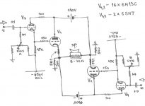
Sampleaccurate since you are lot on the`playground` with Modeling and PSpice Amp simulation,here is one schematic for you if you want to made some virtual(PC) probes. Here the Driver stage suply is conected in different way.(Tube Darlington).Thanks in advance.
Best Regards
Best Regards
Attachments
Sampleaccurate since you are lot on the`playground` with Modeling and PSpice Amp simulation,here is one schematic for you if you want to made some virtual(PC) probes. Here the Driver stage suply is conected in different way.(Tube Darlington).Thanks in advance.
Best Regards
That looks interesting. Does it work - has it been built?
That looks interesting. Does it work - has it been built?
Don't give him any more ideas, Banat. Give him drill bits and a soldering iron. we're all waiting the REAL results!😀
- Home
- Amplifiers
- Tubes / Valves
- What tubes for a OTL tube amp?