Looks like you are getting the hang of it now.😉
I did a similar sim on the tone stack of the Gibson and got similar results, looking at the response of the working unit on a scope gave the same readings.
I was thinking the same thing - these tone controls are very rudimentary and appear to be designed for simplicity and low parts count as opposed to SQ or accuracy.
Member
Joined 2009
Paid Member
controls are very rudimentary and appear to be designed for simplicity and low parts count as opposed to SQ or accuracy.
Of course, it's for an electric guitar, for some serious rock n roll, so you're supposed to be out of your mind and end the gig by slamming it into the ground and stomping on it 🙂
Excellent idea - I'll use the guitar to bust up the amp after my first big concert! Then I'll have a good excuse to build a new and improved model...!
When I started this Ampeg thing I assumed the schematics were correct and complete but I'm having a problem now. The original preamp is on one board and that connects to the chorus board with a 12 position ribbon cable. Now, not seeing any power entry on the preamp board I assumed (again) that power entry was on the chorus board. In a way it is, but it is kinda invisible.
Here's what I figured out:
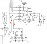
The 2 traces I have marked are supposed to be +44 and -44VDC but there doesn't seem to be an external connection for them. Funny, isn't it?
It took a while for me to figure that out and I have the solution: I will delete the regulator portion of the circuit (my power supply has a regulated +/-15V supply already) and I'll merge the output board onto the chorus board and establish power entry there.
When I started this Ampeg thing I assumed the schematics were correct and complete but I'm having a problem now. The original preamp is on one board and that connects to the chorus board with a 12 position ribbon cable. Now, not seeing any power entry on the preamp board I assumed (again) that power entry was on the chorus board. In a way it is, but it is kinda invisible.
Here's what I figured out:

The 2 traces I have marked are supposed to be +44 and -44VDC but there doesn't seem to be an external connection for them. Funny, isn't it?
It took a while for me to figure that out and I have the solution: I will delete the regulator portion of the circuit (my power supply has a regulated +/-15V supply already) and I'll merge the output board onto the chorus board and establish power entry there.
Already used that in the past, but it did not let me modify circuits (so I cannot experiment with my own) and I did not trust it either 🙂
It would appear there are two connectors one probably connecting to the power amp from which it obtains the higher voltage lines?
It would appear there are two connectors one probably connecting to the power amp from which it obtains the higher voltage lines?
I don't know - some details are missing.
Not a problem though, I've re-done the output side of the chorus board to accommodate power entry:
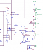
I have kept the balanced output but I'll probably not populate it on this board. I've added an unbalanced output to drive the power amp module and this will be the primary output.
I need to carefully go over the whole schematic looking for mistakes and enter the actual component values as I go as I just copied and pasted most of the parts for the sake of speed. Once that's done I can start the board layout, following the original as closely as possible.
I'm done with the schematic and I've attached it for anyone kind enough to look it over for mistakes (I'm bleary eyed by now). 🙂
Also the link to the original: See page 2.
View attachment AMPEG_CHORUS_SCH.pdf
Also the link to the original: See page 2.
View attachment AMPEG_CHORUS_SCH.pdf
On the original, I can only see two jacks, and they are mixed immediately. But you have sepatate tone controls for "channel A" and "channel B". Confusing.
I'm not sure what you're talking about akis. 🙁 but...
If you are referring to the preamp section, it has has 2 channels - "A" and "B", one is "clean" and the other distorted and a front panel switch (or foot switch) selects one or the other. The two input jacks are high input and low input.
The chorus board has reverb control pots for channel A and B, these are set independently of each other. The chorus board also applied chorus effect to channel A and B, once again independently.
A complex circuit and it has been a real challenge to try to duplicate. Getting the chorus board done will bring me closer to my goal, with just the LED indicator boards to do.
Yes that is what I was asking, I thought A and B would have their own independent inputs, did not check the schematic that well.
Feel my pain:
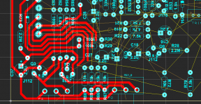
Trying to squeeze everything in. 😱
I would like to get all of the chorus board on one board and not have to split it like I did with the preamp. Looking touch and go at this point.
I haven't been as quick with this one as the preamp either - a little burned out on it but today I received the BBDs and clock generators (MN3007, MN3101) and this gives me some stimulation.
One problem I'm having is that there are some small differences between the schematic and the board layout, mainly where the drain and source are interchangeable on the J112, for easier layout they conveniently switched them.
As seen HERE, I have resumed this project.
Now though, I have shifted gears yet again. 😱
I had too many problems on the (original) massive VH140 clone. I spent most of a day messing with it, messing it up and getting very frustrated. Part of the problem is the way it was laid out - in 3 pieces spliced together with ribbon cable. In the beginning, I should have taken the time to capture the schematic, figured out how EXACTLY it works and made some sensible decisions regarding its layout.
So, I started again (not really, I had started to capture the schematic of the preamps months ago but gave up) and separated the B channel (clean) on its own board:
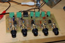
I spent some quality time considering the eventual structure and included some of the "housekeeping" circuitry on this board - the selection circuit to switch between channel A and B, the A/B footswitch jack, the input buffer with the input jacks (high and low) and the output buffer. The row of terminal blocks across the back are for all of these connections plus power input (+/-15VDC).
With this channel finished and tested, my next move is to do channel A. "A" is the distorted channel but is nearly identical to "B", circuit wise.
After channel B, I'll do the reverb board and then finally the chorus board.
For all intents and purposes, this still is a one-for-one clone of the VH140c, just better laid out and easier to test and assemble.
Now though, I have shifted gears yet again. 😱
I had too many problems on the (original) massive VH140 clone. I spent most of a day messing with it, messing it up and getting very frustrated. Part of the problem is the way it was laid out - in 3 pieces spliced together with ribbon cable. In the beginning, I should have taken the time to capture the schematic, figured out how EXACTLY it works and made some sensible decisions regarding its layout.
So, I started again (not really, I had started to capture the schematic of the preamps months ago but gave up) and separated the B channel (clean) on its own board:

I spent some quality time considering the eventual structure and included some of the "housekeeping" circuitry on this board - the selection circuit to switch between channel A and B, the A/B footswitch jack, the input buffer with the input jacks (high and low) and the output buffer. The row of terminal blocks across the back are for all of these connections plus power input (+/-15VDC).
With this channel finished and tested, my next move is to do channel A. "A" is the distorted channel but is nearly identical to "B", circuit wise.
After channel B, I'll do the reverb board and then finally the chorus board.
For all intents and purposes, this still is a one-for-one clone of the VH140c, just better laid out and easier to test and assemble.
Yesterday I laid out and etched the board for channel A. It is slightly less complex than the channel B board, as it does not have the support circuitry.
I had a couple of snags, but nothing major and here it is (on the right) being tested:
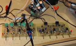
It looks good.
The mistakes I made were on the layout. I assumed the FETs had the same pinout but the J112 is different from the J176. Most of my footprints for layout are handmade, so I just copied the footprint for the J176 to do the J112 and there was my booboo. The fix is to swap legs:
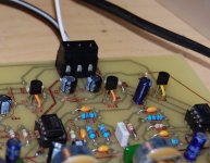
Not a big deal, I've done this before.
The other mistake was the channel indicator LED was routed to the - rail, rather than the trigger voltage (that selects the channel). Easily fixed as well with some solid wire jumpers.
I had a couple of snags, but nothing major and here it is (on the right) being tested:

It looks good.
The mistakes I made were on the layout. I assumed the FETs had the same pinout but the J112 is different from the J176. Most of my footprints for layout are handmade, so I just copied the footprint for the J176 to do the J112 and there was my booboo. The fix is to swap legs:

Not a big deal, I've done this before.
The other mistake was the channel indicator LED was routed to the - rail, rather than the trigger voltage (that selects the channel). Easily fixed as well with some solid wire jumpers.
Onwards!
With the basic preamp section finished and tested (I ran both channels with FG signals to verify waveform and magnitude in comparison to the simulation - very accurate) it's time to turn my attention to the reverb circuit. The tank I purchased (in haste) last year is the Accutronics 9AB3C1B. It has an input impedance of 10 ohms and an output impedance of 2600 ohms. I need to optimize the Ampeg circuit for this tank.
Here is the original:
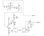
This drive will supply ~32mA to the 10 ohm coil at my supply voltage of 42V. Is this too much current for this coil? Changing R78 from 47R to 56R lowers it down to ~27mA.
I can't find any info on the impedance on the original but it must have been low - 8 or 10 ohms with that much current drive.
With the basic preamp section finished and tested (I ran both channels with FG signals to verify waveform and magnitude in comparison to the simulation - very accurate) it's time to turn my attention to the reverb circuit. The tank I purchased (in haste) last year is the Accutronics 9AB3C1B. It has an input impedance of 10 ohms and an output impedance of 2600 ohms. I need to optimize the Ampeg circuit for this tank.
Here is the original:

This drive will supply ~32mA to the 10 ohm coil at my supply voltage of 42V. Is this too much current for this coil? Changing R78 from 47R to 56R lowers it down to ~27mA.
I can't find any info on the impedance on the original but it must have been low - 8 or 10 ohms with that much current drive.
Last edited:
Happy new year in firstOnwards!
With the basic preamp section finished and tested (I ran both channels with FG signals to verify waveform and magnitude in comparison to the simulation - very accurate) it's time to turn my attention to the reverb circuit. The tank I purchased (in haste) last year is the Accutronics 9AB3C1B. It has an input impedance of 10 ohms and an output impedance of 2600 ohms. I need to optimize the Ampeg circuit for this tank.
Here is the original:
View attachment 203313
This drive will supply ~32mA to the 10 ohm coil at my supply voltage of 42V. Is this too much current for this coil? Changing R78 from 47R to 56R lowers it down to ~27mA.
I can't find any info on the impedance on the original but it must have been low - 8 or 10 ohms with that much current drive.
In order to low impedance of the coil, why don't use a Hammond line whith a more higher impedance?
By the way
On my bilding projects, in the reverberation module, i using the Hammond model 4D83C1B, 620 ohms input, 2250 ohms output, are easy to drive, one single ampop, like tlo71 or ne5534, can drive this type of line, the only thing is the dimension, but in bottom of the one cabinet whit two speakears of 10" or 12", it's right to assembly the line.
On my bilding projects, in the reverberation module, i using the Hammond model 4D83C1B, 620 ohms input, 2250 ohms output, are easy to drive, one single ampop, like tlo71 or ne5534, can drive this type of line, the only thing is the dimension, but in bottom of the one cabinet whit two speakears of 10" or 12", it's right to assembly the line.
Hi julio,
I have the Accutronics unit, therefore I'll be using that. It looks to me that the original VH140c uses a very similar tank.
I'll put it together and give it a try.
I have the Accutronics unit, therefore I'll be using that. It looks to me that the original VH140c uses a very similar tank.
I'll put it together and give it a try.
Moving on. With 2 channels and one reverb tank, there needs to be a way to switch between both and independently set the level of each. The VH140c circuit uses this:
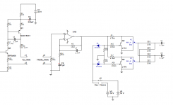
The switch and DC sources are not part of the circuit but give me a way to toggle the voltage from +14VDC to -14VDC at the diodes. This is a very similar way of switching as the A/B channel selection and it uses the "trigger" voltage from that circuit. I see no reason to change or attempt to upgrade this part of the circuit.
The reason for 2 output nodes is that one will go to the chorus section and the other directly feeds the output buffer.
I don't play any instrument, but, I wonder if a foot peddle that is switch (at the top of travel) and rheostat (for max reverberation at bottom) is usable while playing?Moving on. With 2 channels and one reverb tank, there needs to be a way to switch between both and independently set the level of each.
- Status
- Not open for further replies.
- Home
- Live Sound
- Instruments and Amps
- Guitar Amp Design / Build
