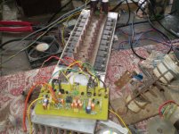
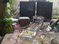
Finally, i could take a few pics of the amp, now it is wired up for test, so the final version will be a bit 'cleaner'.
Comment it, if you want to. And i hope nobody gets angry, because i stole the idea of the transistors arrangement.
ByeView attachment 201520
View attachment 201521
View attachment 201522
Thanks for the pictures, work is clean enough, I just suggest to use some protect circuit (dc protect with triac...),
Regards
Thanks for the pictures, work is clean enough, I just suggest to use some protect circuit (dc protect with triac...),
Regards
Thanks! I will use the protect circuit you provided in this thread, i was just too lazy to hook it up for test run😎
Bye
apex,
2x65 ac?
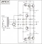
2X65vac give +/-90V DC after bridge rectifier, set output voltage to +/-75V DC with regulator and B500 will be high-end Home, Studio or PA amplifier.
Regards
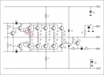
have wonderful day sir apex, one thing i concern base on your schimatic and your sugestion are defferent value of resistor in treple darlington stage, what would be exact or best value of reisistor for the predriever and driver trnasistor, thanks in advance and m ore power...Use 150R for predrivers and 5R6/2W for drivers transistors.
Regards
regards
Attachments
have wonderful day sir apex, one thing i concern base on your schimatic and your sugestion are defferent value of resistor in treple darlington stage, what would be exact or best value of reisistor for the predriever and driver trnasistor, thanks in advance and m ore power...
regards
Both value are OK, use 150R and 5R6.
Regards
have wonderfull day sir apex, i had made the trple darlington stage, very nice sounds, i had take the dc off set of 326mv and the other side 209mv ,my test piont at the BASE of out put trnsistor, and my idling curent is 378mA..my test point at the emeter of out put trns....pls help me if it is normal..if i put r22 and r23 of 1k it is balance dc off set
regads
regads
have wonderfull day sir apex, i had made the trple darlington stage, very nice sounds, i had take the dc off set of 326mv and the other side 209mv ,my test piont at the BASE of out put trnsistor, and my idling curent is 378mA..my test point at the emeter of out put trns....pls help me if it is normal..if i put r22 and r23 of 1k it is balance dc off set
regads
R22 and R23 is for bias set not for dc offset. Do you have 0.5V on R20 and R21 (100R)? If not use 820R for R15 and R16 instead 1k.
Regards
im sorry im wrong, bias i mean, yes sir apex i got .8v at the r20 and r21...my test piont accross the 100R, it is right? pls guid meR22 and R23 is for bias set not for dc offset. Do you have 0.5V on R20 and R21 (100R)? If not use 820R for R15 and R16 instead 1k.
Regards
regards
im sorry im wrong, bias i mean, yes sir apex i got .8v at the r20 and r21...my test piont accross the 100R, it is right? pls guid me
regards
If you want adjust bias, use 2k variable resistor instead R22 (680R), and set abut 8mV on 0,33R/5W resistors, that will be 25mA per output.
Regards
i'm sorry sir if interupt, can i use another type of 2n5401 with the another one but still have the same2N5401 is for VI cut-out protect.
Feedback circuit is important NE5532 can be replaced with another OP amp.
Collector-Base Voltage VCBO -160 V
Collector-Emitter Voltage VCEO -150 V
Emitter-Base Voltage VEBO -5 V
please🙂
i'm sorry sir if interupt, can i use another type of 2n5401 with the another one but still have the same
Collector-Base Voltage VCBO -160 V
Collector-Emitter Voltage VCEO -150 V
Emitter-Base Voltage VEBO -5 V
please🙂
You can use MPSA92 instead 2N5401.
ill put the 2k and then i adjust the bias, going to rigth the negative output verry hot, i return it to left it back to normal temp..... but the i can't goted the 8mV on .33R/5w, but only 356mV, the same w/ the other side....but sounds good....If you want adjust bias, use 2k variable resistor instead R22 (680R), and set abut 8mV on 0,33R/5W resistors, that will be 25mA per output.
Regards
regards
hi apexaudio
greetings can you tell me why i am getting 110 volts output on both collector negative and positive of output transistors using tlo 72 step driver need help please checked everything
thanking you
andrew lebon
greetings can you tell me why i am getting 110 volts output on both collector negative and positive of output transistors using tlo 72 step driver need help please checked everything
thanking you
andrew lebon
thanks sir thats verry helpfull, from now i can star my project, cause i'm verry dificult to find 2N5401, i'll soon post my projecti'm sorry sir if interupt, can i use another type of 2n5401 with the another one but still have the same
Collector-Base Voltage VCBO -160 V
Collector-Emitter Voltage VCEO -150 V
Emitter-Base Voltage VEBO -5 V
please🙂
hi apexaudio
greetings can you tell me why i am getting 110 volts output on both collector negative and positive of output transistors using tlo 72 step driver need help please checked everything please it would be nice if you can explain how
tlo 72 stepdriver works and are there any test voltages for step driver
thanking you
andrew lebon
hi apexaudio
greetings have tried triple ef stage is working in 10 output pair
can i use your IR2117 step driver with this setup as tlo72 step driver is giving
problem waiting for your adivse
thanking you
andrew lebon
greetings have tried triple ef stage is working in 10 output pair
can i use your IR2117 step driver with this setup as tlo72 step driver is giving
problem waiting for your adivse
thanking you
andrew lebon
Attachments
protect circuit works
andrewlebon pls check mail i sent some picture and my new Apex protect is working without error
hi apexaudio
greetings have tried triple ef stage is working in 10 output pair
can i use your IR2117 step driver with this setup as tlo72 step driver is giving
problem waiting for your adivse
thanking you
andrew lebon
andrewlebon pls check mail i sent some picture and my new Apex protect is working without error
hi apex audio
greetings want to ask you that can you please tell me if i am
wrong
1 pin 7 of ic TLO72 should go to base of transitor BF422 but 5 no pin is going to base
2 from 5 no pin 10K resitor should be ground
3 1 no pin of ic TLO 72 should go to base of transistor BF423 but 3 no pin is going to base
4 3 no pin should be ground via 10 K RESITOR
PLEASE TELL ME IF I AM CORRECT FOLLOWING SCHEMATIC
hopimg you can help me
thanking you
andrew lebon
- Home
- Amplifiers
- Solid State
- 500W PA amplifier with Limiter