I have always been puzzled by valve heatsinks. Unless silicon grease is used, they will make only patchy contact with the glass so there will be cool spots and the rest hot - a recipe for problems? Glass is a poor conductor of heat, so even the contact points won't cool it very much. Most of the heat gained by the heatsink will be radiant heat, which was already outside the valve anyway!
The solution to valve cooling is either ceramic valves or air flow. Air does contact the whole glass fairly uniformly so it can take the heat away. Maybe Wavebourn should be looking for a very quiet fan?
I agree and don't buy into the whole "tube heatsink" thing. I think it's just more hifi snake oil at best. Just put the tubes in and let them do their thing. Old tube radios have lasted many years with the original tubes in them. In fact, my father just rebuilt a 60+ year old Zenith with all the original tubes and they all measured almost perfect. The owner says the radio has been in the family the entire time and has been used almost daily for several hours a day up until a few years ago when the caps and selenium rectifier went in it.
That's proof enough for me to not need tube heatsinks.
Don't agree with the idea. I tried this on an EL34 and after a hardish session the tube packed up with cracks in the glass where the sink was fixed. Slight expansion/ contraction in the zone where the sink doesn't quite make contact all the way round is asking for trouble.
I've always thought tubes should get hot enough +100°C for the Getter to function properly.
I've always thought tubes should get hot enough +100°C for the Getter to function properly.
Some getters require heat, others don't.
I suspect the main effect of a "tube cooler" is to heat up the glass by preventing convection and reflecting more heat back in. Fortunately much of the reflected heat will be stopped by the glass and not contribute directly to a hotter anode.
Question: how does heat get away from the anode?
Answer: In glass valves almost all by radiation, plus a small amount via conduction through the pins. There is no convection inside the valve, as there is no gas there.
Q. As there is no convection, and glass is transparent, how come it gets hot?
A. Glass is not fully transparent at infra-red, so some radiation comes through and some gets absorbed and heats up the glass. (I'm not sure of the proportions)
Q. How does the glass lose heat?
A. Partly radiation - both inward and outward. Partly convection. (ditto)
Q. How do you cool glass?
A. Blow cool air on it.
Q. What about the radiation?
A. Don't reflect it back into the valve. Either let it spread out into empty space, or absorb it in something black which will then get hot but which is far enough away that its own radiation mainly misses the valve.
Go with the chainmaille. Even world's dumbest idea, you will look cool doing it!
Claim all sorts unscientifically unprovable benefits and act like everyone else is
too ignorant or poor to play in the same league. Thermodynamics be damned.
Claim all sorts unscientifically unprovable benefits and act like everyone else is
too ignorant or poor to play in the same league. Thermodynamics be damned.
3rd the peral tube coolers. The recent redesign has made them even better, Bill has documented the actual measured results.
I believe the tube cooler papers have been recently revised (the above are old):
PEARL Lit Archive
dave
I believe the tube cooler papers have been recently revised (the above are old):
PEARL Lit Archive
dave
Aren't the Pearls made of copper. Can they be bonded to ground to act as a EMF shield? If so I would think that they would perform better thermally than a typical can shield.
Aren't the Pearls made of copper
Copper yes, now powder coated.
dave
In the Valve Age, there was no need for such trinkets like "tube coolers," because tubes work just fine without. Want more power dissipation? Choose a tube with a bigger glass envelope or a ceramic tube with the anode brought out.
I wonder what has changed that they'd be needed now?
Of course a tube clothed in chain mail or silly wrinkles makes a nice conversation topic when one is entertaining guests who are no longer impressed by the sight of an unadorned vacuum tube ;-)
I wonder what has changed that they'd be needed now?
Of course a tube clothed in chain mail or silly wrinkles makes a nice conversation topic when one is entertaining guests who are no longer impressed by the sight of an unadorned vacuum tube ;-)
Coolers were used in some equipment I saw, but they looked more like the pearl coolers. I could immagine these would work better at NOT reflecting IR back as long as air convection on the outside of the tube was sufficient (amazing how many DIy designs completely forget about this...). The surfaces of the cooler are not parallel to the internal structures so mostly they reflect IR to each other creating a 'trap' of sorts.
Lowering the envelope temperature does indeed extend tube life. In fact, lowering the pin-glass interface temperature does so even more, the reason being the glass and pins outgas less and the differing temperature dilation coefficients are less of a problem (these ultimately result in gaseous / bad vacum tubes because of vacum loss at the glass-pin seal).
In short, a tube cooler has to be properly designed, and even them it doesn't do it's job magically on its own - it's purpose is to absorb radiated heat in order for it to be dissipated mainly by convection. if there is no airflow, or there are other heat sources nearby, or convection is not laminar (instead has vortexes and pockets) they won't be able to do their job.
An externally hosted image should be here but it was not working when we last tested it.
If you put the tube with a PEARL tube cooler in a chimney it can be even more effective.
dave
I looked into the pearl coolers.....17 bucks a pop...almost as much as the tubes they are cooling.....I have 20 power tubes...10 on each amp...decided on a metal 4 inch fan for each amp.....I have the fans spinning slower using a step down xformer.....the fans work.
At the risk of appearing presumptuous, I'm going to lurk this thread for a while longer as I don't have time ongoingly to address points made by various posters.
To date however several folks have made statements that are simply not correct. A careful read thru my paper on the matter of tube cooling written some 20 years ago will clear up a lot of misconception.
And do note please, the matter of cooling tubes' glass is neither frivolous nor new, having been developed by the military and the aeronautics industry in the early '50s
On my site, the relevant link is:
http://www.pearl-hifi.com/03_Prod_Serv/Coolers/PEARL_Tube_Coolers.pdf
Now, back to the NaCl quarry . . . but not before saying that tubes run -hot- die young, without exception.
12AX7s OTOH will live forever because at about 4W max dissipation they can't work up any sort of glass damaging temperature; and it's the soft glass that's the culprit, not the glass-to-metal seals.
That's why Bendix made the envelopes for all those fabulous, hi-spec, long lived Red Bank tubes like the 6900 and 6384 out of . . . wait for it . . . P Y R E X.
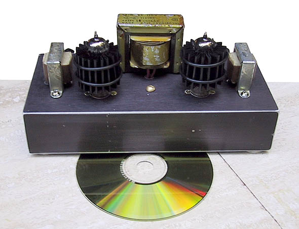
The cooler on my initial picture actually was taken from some surplus military transmitter. Being black, it does not reflect rays; it absorbs them, and as soon as it's temperature is higher than ambient it creates convection the cools it down. It is made of especially formed copper alloy, so it conducts heat well from internal to external surfaces. It can't break the glass because it acts like a spring, absorbing heat from the glass as well.
The military tube "coolers" that I've seen did not have fins. They were a simple metal tube, with a springy insert that pressed against the tube with little leaf spring fingers, keeping it centered. With maybe a 1/4 inch gap from glass to metal tube. The springs only had tiny end edges against the glass tube, clearly NOT intended to convect heat from the glass. The tube acted as a chimney for air passing thru chassis holes around the base of the tube. The bottom chassis was pressurized by a fan. The conformal air flow would provide uniform cooling of the glass evelope. This was clearly a very well thought out "cooler" approach and should be easy to emulate now if one puts a fan in the base to pressurize it.
The "cooler" tube needs to extend down to the base to entrap the air flow from holes around the tube socket. I just mount the tube socket with some 3/16 inch spacers below the chassis and the air flow cools the socket and pins too on the way up around the tube. No need to drill extra air holes then. Especially with Compactron sockets (Sweep tubes) which have a big hole in the center. Could probably even get away with a "cooler" tube that only comes half way up the glass tube side, then you can still see the glow. I don't use any thing more than just the recessed sockets with the chassis fan. But then I haven't tried doing a "Tubelab" glow test on my tubes either.
The earlier example of a 4X150 type tube is off base here for glass tubes. There the plate is heat conducive metal and the fins are silver soldered to the plate. Pressurized air passed thru the fins. Clearly designed for convection from the get go.
Last edited:
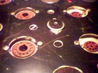
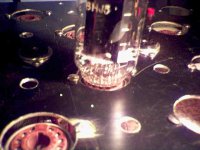
Here is a pic of some recessed sockets for use with pressurized chassis air flow. I checked the socket spacers and they are actually 1/4 inch. You will also note that the experimenter chassis uses interchangeable socket assemblies for any type socket. Ie, 7 or 9 pin or octal or compactron fit the same chassis holes by means of mounting plate adapters.
Attachments
Last edited:
If tubes needed cooling artifacts, they would have been designed and implemented a long time ago. Except, of course, for HF high power tubes.
Snake oil and bulldust.
Serge😛
Snake oil and bulldust.
Serge😛
If they were used in old military equipment, they were probably there to protect the surrounding components from heat, rather than the tube itself.
If I wanted to make a tube cooler I'd make my own from a length of alu pipe. Keep the inside shiny to reduce IR re-emission. Paint the outside a dull black, and drill some holes near the bottom end. Place the pipe excentrically around the tube: we don't want to place the anode in the focus of the mirror that is the inside of the pipe.
If I wanted to make a tube cooler I'd make my own from a length of alu pipe. Keep the inside shiny to reduce IR re-emission. Paint the outside a dull black, and drill some holes near the bottom end. Place the pipe excentrically around the tube: we don't want to place the anode in the focus of the mirror that is the inside of the pipe.
And do note please, the matter of cooling tubes' glass is neither frivolous nor new, having been developed by the military and the aeronautics industry in the early '50s
Hifi audio, of course, being a prime example of a military or aeronautic application?
Aeronautics use 400Hz power distribution which is arguably superior (more dB ripple rejection for the same money) to 50/60Hz, but I don't hear anyone insisting it be used in hifi audio.
On my site, the relevant link is:
http://www.pearl-hifi.com/03_Prod_Serv/Coolers/PEARL_Tube_Coolers.pdf
I am sorry, but either it's peer reviewed, or it's an ad. You can't credibly say it's neither.
I have read the Pearl stuff, and I remain unconvinced. Most of it is describing the well-known problems of hot glass, and the benefits of cooling. Very little is said about how the Pearl coolers actually work. The paper admits that glass is a poor conductor of heat; it forgets to admit that this means that contact cooling will not work too well. They may use a chimney effect, but that was not clear. It contains a minor mistake: KT valves came from Marconi-Osram, not Mullard-Osram.
A claim that the military do something is not necessarily proof that it works. The TTFD antenna (broadband, but rather inefficient) was a US Navy project. I once saw a 'research' paper funded by the military which confused input impedance with transfer function: it claimed to measure IP3 of an RF amplifier by measuring the power dependence of the reflection coefficient of the input port. The daft results arising from this confusion were described by the authors as being due to calibration problems! This is the sort of thing which your tax dollars are funding.
A claim that the military do something is not necessarily proof that it works. The TTFD antenna (broadband, but rather inefficient) was a US Navy project. I once saw a 'research' paper funded by the military which confused input impedance with transfer function: it claimed to measure IP3 of an RF amplifier by measuring the power dependence of the reflection coefficient of the input port. The daft results arising from this confusion were described by the authors as being due to calibration problems! This is the sort of thing which your tax dollars are funding.
- Home
- Amplifiers
- Tubes / Valves
- Heatsinks for tubes?