Just curious, since when R21,R22 & C9 as current booststrapping network is better solution than regular current source with one or double BJT's. Is this only a fancy result of simulator measurings or really better choice by listening tests. 😕
Just curious, since when R21,R22 & C9 as current booststrapping network is better solution than regular current source with one or double BJT's. Is this only a fancy result of simulator measurings or really better choice by listening tests. 😕
Simpler and better sounding , ask DX (destroyer X). People make fun of the primitive bootstrapped current source but it is more musical. Combine that with the PPM blameless w/ TMC and you have utter perfection.
OS
Simpler and better sounding , ask DX (destroyer X). People make fun of the primitive bootstrapped current source but it is more musical. Combine that with the PPM blameless w/ TMC and you have utter perfection.
OS
Hi OS,
Due to my low level of understanding I am not in the best position to sort out what you recommend. I do believe that you are saying the BX1.3VB is your best sounding amplifier project. Is that true?
Thanks,
Mark
Hi Oz,
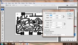
I'm ging to make your BX1.3VB next however, I just discovered the file for the BC version is set at 96 dpi causing the print to be massive.
Pete.
I'm ging to make your BX1.3VB next however, I just discovered the file for the BC version is set at 96 dpi causing the print to be massive.
Pete.
Hi OS,
Due to my low level of understanding I am not in the best position to sort out what you recommend. I do believe that you are saying the BX1.3VB is your best sounding amplifier project. Is that true?
Thanks,
Mark
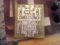
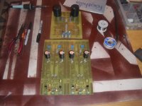
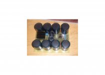
As it is the BX1.3 beat out the luxman , the regular blameless , and any of the symasym variants I have. And that is with a juryrigged BX1.1 board. I m hard at work now ... (perfect etch - pix 1 ) and the whole "test bed" (pix 2) to give the best of the sym's (my new CX1.3 - goldmund killer) and the BX1.3 a "head to head" comparison. I can do this easily with my modular system.
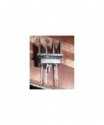
I even will FET both amps to see what's up (pix 3). No one in "carlo's camp" has tried to do that. Both my CX and BX have cascoded inputs , so no problem. I would not be doing this or putting the BX up against the near perfect CX if the BX wasn't up to it.
The "test bed" will be 100K uf 75-0-75v 30 amp power supply running 2 -250 watt Very high current self EF2 stages., ALL caps are seriously derated (100v and 400v), all rail traces are 12mm +. Wires will be either 14 or 12 gauge audio grade color coded with faston terminals. The Output stage is now 2 X 4 pair 21193/4's so 4R loads will be no issue. ONE LOUD AMP. we'll see how these sound at 50-70vRMS !!
OS
Attachments
Hi Oz,
I'm ging to make your BX1.3VB next however, I just discovered the file for the BC version is set at 96 dpi causing the print to be massive.
Pete.
Pete,
I had the same problem when I printed the BX1.3VB. In the end, I used M$Paint on Vista & used a scaling of 16% or 17% and the lead spacing were all OK.
BX does sound better than GX on my setup.
Cheers, Stanley
sorry to know.what function for gx circuit?and pb120n must needed gx?
You can plug any of the "X"s into any of the "PB"'s. VAS currents and everything else is standardized. You can swap out amp voltage stages as easy as changing a sound card in a PC. 🙂
OS
Pete,
I had the same problem when I printed the BX1.3VB. In the end, I used M$Paint on Vista & used a scaling of 16% or 17% and the lead spacing were all OK.
BX does sound better than GX on my setup.
Cheers, Stanley
Does it sound better than any other amp you have??
OS
Pete,
I had the same problem when I printed the BX1.3VB. In the end, I used M$Paint on Vista & used a scaling of 16% or 17% and the lead spacing were all OK.
BX does sound better than GX on my setup.
Cheers, Stanley
as far as the BX sizing , look at my PSP detailed properties ... 4 X 3" (100 x 75mm) 256 color single layer 600dpi image , PSP never lies. You need a better graphics program. I can print from what is below absolute ... no aliasing at the max HP 600dpi.
OS
Attachments
Hi Oz,
The problem is with your modified version for using BC transistors.
Here is a psp image.
I'm trying to resize now, hopefully my netbook has enough power...
Pete
No good, not sure what I'm doing
The problem is with your modified version for using BC transistors.
Here is a psp image.
I'm trying to resize now, hopefully my netbook has enough power...
Pete
No good, not sure what I'm doing
Attachments
Last edited:
yes , I will fix that. I did the BC version quick , as I did not like SNG's quick fix.
Completed the first sprint layout board (PS100) , and it is factory quality (pix1).
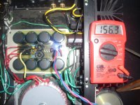
I did "do" the snubbers , even as certain audiophiles say they are not needed. 600 v @ .05uF should do nicely (pix2). I went for a 50A heatsinked bridge on this "final" model (pix3).
A word of caution , (Pix4).. shows it up and running ..PHEWWW! , I am SCARED of these power supplies. I have blown screwdrivers to molten bits and got shocked .. it is like a "knockout punch" when 156v DC passes through you. 😱
156v is my no load voltage, that drops to 150v with the drain (70mA X 16) of class AB bias. The most I could ever load it down was to 148V at nuclear levels. My first cap multiplier (1st order) would show about 20mv ripple on the voltage modules at this level. This time around I have 2nd order multipliers and larger caps on the PB250's. I will show them next. 🙂
repeet .. here is the BX with BC trannies , below. 600 dpi /100mm X 75mm.
OS
Completed the first sprint layout board (PS100) , and it is factory quality (pix1).
I did "do" the snubbers , even as certain audiophiles say they are not needed. 600 v @ .05uF should do nicely (pix2). I went for a 50A heatsinked bridge on this "final" model (pix3).
A word of caution , (Pix4).. shows it up and running ..PHEWWW! , I am SCARED of these power supplies. I have blown screwdrivers to molten bits and got shocked .. it is like a "knockout punch" when 156v DC passes through you. 😱
156v is my no load voltage, that drops to 150v with the drain (70mA X 16) of class AB bias. The most I could ever load it down was to 148V at nuclear levels. My first cap multiplier (1st order) would show about 20mv ripple on the voltage modules at this level. This time around I have 2nd order multipliers and larger caps on the PB250's. I will show them next. 🙂
repeet .. here is the BX with BC trannies , below. 600 dpi /100mm X 75mm.
OS
Attachments

Last edited:
.. it is like a "knockout punch" when 156v DC passes through you. 😱
😀
I haven't been lucky enough to have experienced that pleasure (yet)

Looking sweet!

I like those inductors, though I'm not sure if they have enough inductance - maybe try a hunk of steel in the centre to bump that up, see if it makes a measurable difference.
156v is my no load voltage, that drops to 150v with the drain (70mA X 16) of class AB bias.
OS
168 Watts TDP at iddle ?.
That s as much as a 2X50 W rms amp
at full power, supply losses included....
168 Watts TDP at iddle ?.
I posted earlier, in haste (my math was off too 😱 ), but your calculation is a bit off.
150 is rail to rail, so it would be 84 watts dissipated.
168 Watts TDP at iddle ?.
That s as much as a 2X50 W rms amp
at full power, supply losses included....
Huh ?? each op is 70ma (.27R- 16-17mV) , each (channel) draws about 1/4 amp per rail -per side. (measured it)
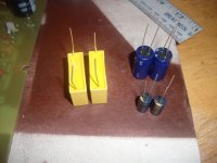
Next is the fun part (scary ,too) etch and fire up the BX 1.3/pb250 combo with the good caps (cost more) ... 4.7u 100v poly's (big yellow ones) , the "gold" panasonic EE's (bootstrap - 100u) and Nichicon low esr NP 220uF's (DC block).
Nothing but the best for my "patchwork/blame ES" (BX1.3) - see , I give credit where it is due ! oh , and the E. Stuart / baxandall TMC implementation. 😀
OS
Attachments
😀
I haven't been lucky enough to have experienced that pleasure (yet)
Looking sweet!
I like those inductors, though I'm not sure if they have enough inductance - maybe try a hunk of steel in the centre to bump that up, see if it makes a measurable difference.
The inductors , according to a web based "coil calc" are about 10uH each. The original performed flawlessly (below) . I will give (trade) the one below to somebody in the us./ canada (where ever a 5$ flat rate box will go). I will donate /trade the 2 PB250's as well ,once I strip them. I will leave most resistors, jumpers , fastons. Caps and semi's will be reused.
OS
Attachments

the 9ppm amp ... will it astound ???
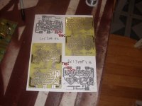
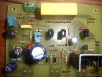
The BX's are done .. First high density boards I have outputted from sprint layout. THEY LOOK GOOD !! 🙂 SNG already built the BX with this layout so I know I am good to go. Tweaking the sim (cascode voltage , CCS current) on the BX , I decided to slightly change the cascode divider to 17v @ 70v rail / 10v @ 40v rail. On mine (below- 1 and 2) I used the hitachi 2sc2229's that Capt. Grogg gave me for the CCS , 2sa992/2sc1845 for cascode/current mirror and those wonderful SS9014 low noise BJT's for differentials. I went through 20 SS9014's and Hfe was only off by .1 Hfe on the DMM's scale ... closest I've ever seen for 20 devices tested consecutively. Praise Fairchild !! 😱
With the sim tuned up with my slight changes , I get 9-10 ppm all the way to 10K (Below attachment 3) , all at 50 watts. I CAN'T wait to fire these up tomorrow on my new 250w OP stage !! 😎
Now everyone at DIYA is arguing about the origin of the "devastatingly effective " TMC. I think besides Baxandall , (who is deceased) and E. Stuart both independantly came to the same conclusions. "The Baxandall papers" ,ooooooH !! ... were just recently released. At least mr. Stuart shared the "goods" , the book writers would of kept people "baited" and say " a new secret inside " to sell the next book. Oh , well the "cat is out of the bag" NOW... 😀 Pick your flavor of cherry or chocolate TMC !
OS
Attachments
- Home
- Amplifiers
- Solid State
- The MONGREL (supersym II)