Hi All,
Completely new here,
I've gotten hooked on this DIY audio amp building.
My goal is to replace a Marantz 2226B with a DIY integrated amp. So far I have had good results, but not enough to beat out the Marantz ( it may never happen). I have 90db speakers and can blow go too loud with 4-5 watts. Personally I like lower watts.
So I have tried the Chip amps...but I love the simplicity of a Single ended amp. To me there's no sense in creating a class A/B chip amp if I already have a Class A/B amp...that sounds good.
So I want to find/ develop a circuit that uses a single gain stage single ended transistor amplifier. I had a darlington amp work...but not enough volume. I'm trying to stay away from mosfets- I always come up with more distortion on the simulator with mosfets...and seems to give me a headache when played...awsome transparency though...just too sharp on the highs.
So am I trying to do the impossible? I don't want to rock the windows to a rattle...detail is more important.
Thanks for reading this and for any help you may have.
Yes.
Here are a couple of references for you to look at:
http://www.passdiy.com/pdf/zenamp.pdf
Death of Zen - A new Class-A power amp
Here are a couple of references for you to look at:
http://www.passdiy.com/pdf/zenamp.pdf
Death of Zen - A new Class-A power amp
And if you do want to pursue a bipolar transistor amp (and you'll end up with three stages), the design at this site is well regarded and there are many references to it on this forum:
The Class-A Amplifier Site
Or if you change your mind about FETs the passdiy site has many refinements to the Zen amp that you may find interesting.
Better start saving up for big heatsinks and transformers.
The Class-A Amplifier Site
Or if you change your mind about FETs the passdiy site has many refinements to the Zen amp that you may find interesting.
Better start saving up for big heatsinks and transformers.
Better start saving up for big heatsinks and transformers.
This is the circuit I used for the mosfet amp- DIY Class-A 2SK1058 MOSFET Amplifier Project
I really do like the sound for what it is...I made some modifications and replaced the Pot with two resistors who's values were determined by my playing with the simulator.
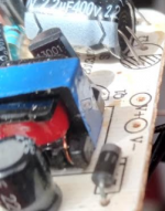
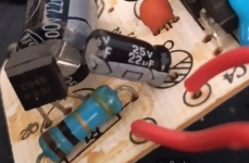
Interestingly enough, I cheated and bought a $15 switching power supply. It powered one channel with this switching power supply- 24V 2.5 Amp. Amazingly, when I turned it up all the way with no music, you could here absolutely nothing from the speakers...zero hum. No filtering capacitors needed. Virtually no heat.
I ran two channels on a 24V .7 amp switching supply. Didn't sound bad with "how to Tame Your Dragon" movie...even though it does best with music.
I have a 24V 5 Amp switching supply if I can't get enough out of the 2.5amp supply. The heat is generated by the resistor in this circuit...and it runs HOT. after an hour of play, I could put my hand on the BUZ 11 mosfet- hot to the touch and a warm heatsink.
Luckily I got a ~30# heat sink out of a VFD that controled motors running off of 450V. I've been cutting it up into usable sizes so I wouldn't have to use a fan.
Strange that you say that .I haven't built any SE resistor loaded mosfet amp ,which is remarkable for its high 2nd harmonic distortion (should sound better on higher loads),but for the power supply usually I see often some very huge caps ,also with a 1-2 Ohm resistor or regulated .
I know in multism spice simulator the distortions were 10- 15% at full volume. It came down to a more manageable .9% around 15%. The crazy thing is I couldn't get past 25% without good chance of waking the kids in the other room...so the design is for less 4.8watts I'm probably using 2 watts with a 2.5 amp source. The speakers are Boston Acoustics A100's - 2way 10" x 1" and 90db acoustic suspension. I wouldn't consider these the most sensitive speakers...but it does the job.
However, with a BJT darlington or BJT...I'll get the same voltages/ amps...but not near the volume. That was on a 89db speaker though.
However, with a BJT darlington or BJT...I'll get the same voltages/ amps...but not near the volume. That was on a 89db speaker though.
wow ! you're deranging me from my 'audio beliefs' 😛
Also a box containing a 10" woofer with a 1" dome tweeter !!!
quite difficult to have 'merging emissions' from two drivers with such different size -at least the tweeter needs a large mouth waveguide .
In hi-fi ,to avoid distortions and having the amplifiers never clipping ,it is better to have plentiful of Watts ...about 100-200 should be enough 🙄
😉
Yes...10" x 1"...and I'm not sure how they did it, but it puts out full spectrum sound better than some other speakers I have thought about buying. Only the $3k each Martin Logan electrostatics came close...but had problems transitioning to the woofers for bass.
I know that this was Boston Acoustics "no comprimise" speaker. The larger baffle helps and plus it is an acoustic suspension- detail is more prominent than heavy bass and loudness. These are not "party" type speakers. You don't get as heavy bass as in a ported speaker.
This is one of the reasons I believe you can get great sound using lower watts. I used to think more watts was better...then my vintage 1977 25watt/channel Marantz blew away my 2006 80watt/channel Marantz receiver. Both in detail, full range and volume.
I truly believe in using less watts. If your speaker is rated at 90db...then 1 watt at 3ft = 90db of sound. Creating an amp that doesn't clip at these levels is doable...I just want to do it using a single stage...and BJT's will produce down to 1.79% THD full volume with no clipping...but .05% at 60%...I just need more power, 8 watts is more than enough.😉
Forgive my ignorance,
but may I ask why?
It swithces at MHZ...and handles 2.5 amps.
I also have one that is +12, -12 at 5 amps.
but may I ask why?
It swithces at MHZ...and handles 2.5 amps.
I also have one that is +12, -12 at 5 amps.
Have you seen this one?
Project 83 - MOSFET Power Follower
This may be the best choice for you if you don't mind an amp that uses small dignal BJTs and Power MOFETs, is very fast and stable, clips smoothly, reproduces bass as good as highs, and sounds like magic in the midband.!. Well, these are the usual characterisitcs of any good SE class-a amp that runs in Common Drain config. Oh yes, it has Zero global NFB. 😎
rcollege,
you are about to build a nice sounding single-ended amp, right? The practical disadvantage is the need for large heat sink, large transformer, large capacitor bank and preferably even two large chokes. Switching power supply is not suitable.
you are about to build a nice sounding single-ended amp, right? The practical disadvantage is the need for large heat sink, large transformer, large capacitor bank and preferably even two large chokes. Switching power supply is not suitable.
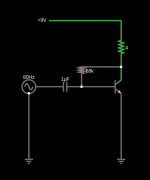
Common transistor amp experiment
This video describes the testing of a single transistor amplifier. Worth trying.
Adventures in a one transistor audio amplifier - YouTube
Transistors are very commonly found in phone chargers and other things. I opened up a phone charger to find two of these:
C945
One suggested circuit : Low impedance input preamplifier | microphone speaker circuit | ElecCircuit.com
13001
Attachments
Last edited:
The circuit in this video works, but there is no increase in sound. What could be wrong? I could not get the required 95K resistor, could that be the problem? Using a 10 Ohm.
How to make mini amplifier use c945 transistor,diy amplifier - YouTube
Here is the circuit in a circuit simulator:
How to make mini amplifier use c945 transistor,diy amplifier - YouTube
Here is the circuit in a circuit simulator:
Attachments
Last edited:
The feedback resistor is just forming a voltage divider with the output.
A 10R cannot be used instead of a 95k, there won't be any voltage gain.
What is the DC voltage from the base to emitter? If not 0.6VDC, the transistor is not working.
A 10R cannot be used instead of a 95k, there won't be any voltage gain.
What is the DC voltage from the base to emitter? If not 0.6VDC, the transistor is not working.
Last edited:
Did some testing : 9V connected to collector, and only an LED connected in series, the LED lights up. Current passes through the 13001 transistor even without any base current applied.
Next: c828 same thing.
This means these transistors are defective, right? The datasheet for the 13001 says it can take 400V at the emitter. Removing these involved a lot of heat and a soldering gun.
Time to try brand new transistor sealed new.
Next: c828 same thing.
This means these transistors are defective, right? The datasheet for the 13001 says it can take 400V at the emitter. Removing these involved a lot of heat and a soldering gun.
Time to try brand new transistor sealed new.
This is really getting to me now. I really would like a simple transistor based amplifier, what could be simpler? The transistors I am testing are all coming out bad, even the sealed one from 30 years ago named NTE123AP from NTE Electronics New Jersey.
All of them fail this test one way or the other:
Transistor Test For Identifying Terminals,Type & Condition - All About Engineering
The mulitmeter shows high resistance when it should not and low when it should not.\
As a last resort, I will set up the following simple circuit to see if the current passes through and lights the LED without any base current input. If the LED lights the transistor is bad.
+ 9V o-------- o Collector Emitter o-------o LED o-------o -9V
Then I go out and buy some new transistors. By the way the middle pin is not always the base. I had to find this out the hard way,
Transistors have different pinouts.
Check the handbook.
In addition, transistors are of different conductivity (NPN and PNP).
Transistors are bipolar (BJT) or field-effect based (FET).
Check the handbook.
In addition, transistors are of different conductivity (NPN and PNP).
Transistors are bipolar (BJT) or field-effect based (FET).
The pinouts are sorted out from the on line data sheets. These are all NPN.
I dont think these are FET at all, so that leaves me with the test. Must not exceed 300 mA on some of these which means I have already exceeded this in my tests. Oh well.
I dont think these are FET at all, so that leaves me with the test. Must not exceed 300 mA on some of these which means I have already exceeded this in my tests. Oh well.
- Home
- Amplifiers
- Solid State
- Single gain stage transistor amplifier.