Salas
Xpovia Polla !!!
Also attached is a copy of the new document that I'm working on. IT'S STILL A Beta. Any suggestion are welcomed
Pete
Wow, impressive work Pete thank you very much, please could you add to Wiki page?
Cheers
Felipe
I used a 15 nF cap with a .75nF trimmer. what effect is more/less capacitance? when redo the enclosure I will snap some photos of the boards.
Evan
Evan
Hi Guys,
I have a few questions for you.
I read the pete's document and I would like to know if I have the good version for my photo stage? see this link: http://www.diyaudio.com/forums/analogue-source/129126-simplistic-njfet-riaa-307.html#post2090662
second question: I would like to know what's the best after the diodes bridge between CRC ( 4700uF-resistor?-4700uF BHC) or 2*4700uF only?
thank you! Maxpou
I read the pete's document and I would like to know if I have the good version for my photo stage? see this link: http://www.diyaudio.com/forums/analogue-source/129126-simplistic-njfet-riaa-307.html#post2090662
I believe all versions are good. Different versions differ only by gain and JFET's IDSS.
Hi Guys,
I have a few questions for you.
I read the pete's document and I would like to know if I have the good version for my photo stage? see this link: http://www.diyaudio.com/forums/analogue-source/129126-simplistic-njfet-riaa-307.html#post2090662
second question: I would like to know what's the best after the diodes bridge between CRC ( 4700uF-resistor?-4700uF BHC) or 2*4700uF only?
thank you! Maxpou
Not only good but tailored to your stash and application. Its what a general guide just can't cater for. This is not a BJT phono with defined closed loop gain (global feedback). IDSS, bias, and gain are a balancing and channel matching act. Takes some individual care.
*I would avoid the resistor.
I used a 15 nF cap with a .75nF trimmer. what effect is more/less capacitance? when redo the enclosure I will snap some photos of the boards.
Evan
More is duller, less is brighter.
I believe all versions are good. Different versions differ only by gain and JFET's IDSS.
Correct.
May I ask why?
Avoiding damping the caps further than their own ESR when not needed. Small uH RF coil between can do a good job without the resistance.
Wow, impressive work Pete thank you very much, please could you add to Wiki page?
Cheers
Felipe
Hi Felipe
What is the Wiki page ?
Salas
Xpovia Polla !!!
Also attached is a copy of the new document that I'm working on. IT'S STILL A Beta. Any suggestion are welcomed
Pete
Hi Pete
Congratulations for the splendid work 🙂
There seems to be a misprint regarding Q5 on the text and Q6 on the riaa schematic.
Can you elaborate on why did you choose 470uF for C6 on the BC550C base bias circuit ?
In your pdf text, you state you are the developer of the circuit... Why not use 220u as in the previous Salas schematics ?
I am also very interested in the Low MC pre pre that seems a good alternative to a SUT.
Did you build one of those ? Why using a 7809 and not a Salas shunt there ?
Regards
Ricardo
Hi Felipe
What is the Wiki page ?
Hi Ricardo
Here: Salas Simplistic NJFET Riaa Schematics - diyAudio
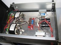
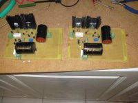
Finally found some time to begin my second RIAA.
PS will be in an external box with 2 rcore transformers and an CL - 4700uf plus 10H. Final C 10000uF will be on the RIAA box with the V 1.2R shunts, which I completed and tested. Vin loaded is 52V and Vout 42V.
For the RIAA - it is going to the 57db for my Shelter 901 - I have already matched some 170 BL at about 8.5mA, but I also have a stash of V's. I will measure some and see how many I can match.
Also waiting some teflon capacitors from the states.
Attachments
In the input I will have a 10000uf Mundorf. In the output, you mean th 47uF?
This one is a Panasonic for now - that's what I only have now - but I want to replace it with something better.
This one is a Panasonic for now - that's what I only have now - but I want to replace it with something better.
- Home
- Source & Line
- Analogue Source
- Simplistic NJFET RIAA