Thanx
Ty mile now ill try to connect Step drive to my B 500
pls check if anything wrong with my work.
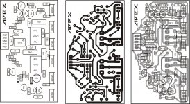
TL072 Pcb and Component Layout.
Ty mile now ill try to connect Step drive to my B 500
pls check if anything wrong with my work.
Attachments
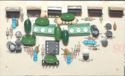
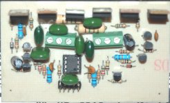
so the -ref is i.c.pin1,2,3,TL072 classH Step Driver: Pcb and Component Layout.
and +ref is ic,6,7,8,
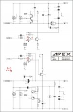
the schematic must be?
Attachments
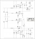
apex,
if the above is now correct,why pin 5,3 to bf422/423 base
it must be pin 1,7 to bf's base
I made drawing mistake, go to post #923.
Regards
thank you apex,I made drawing mistake, go to post #923.
Regards
now its clear for me
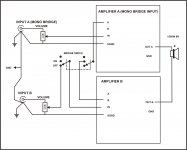
apex.for b500 amp what function at input for a and b?and can change 2sc5200 with mjl4281a?TL072 classH Step Driver Schematic + PCB
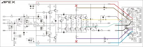
apex.for b500 amp what function at input for a and b?and can change 2sc5200 with mjl4281a?
A and B use for bridge mode, MJLs can be used instead 2SA/SC
Attachments
Ty mile now ill try to connect Step drive to my B 500
pls check if anything wrong with my work.
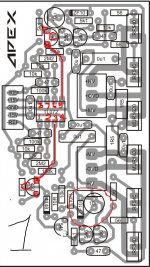
Use circuit from post #928, and correct pins layout for TL072 (drawing mistake)
Regards
hi irvynejay
greetings you are using .1 100 volt green caps 2 .1 should be 250
volts see pcb component layout the BIGGER .1 ARE 250 VOLTS ON 120 VOLT
SUPPLY CHANGE THEM
thanking you
andrew lebon
greetings you are using .1 100 volt green caps 2 .1 should be 250
volts see pcb component layout the BIGGER .1 ARE 250 VOLTS ON 120 VOLT
SUPPLY CHANGE THEM
thanking you
andrew lebon
tlo2
ok ty for the advice andrew ..im still waiting for the one i ask on you andrew pls check pm if you have timehi irvynejay
greetings you are using .1 100 volt green caps 2 .1 should be 250
volts see pcb component layout the BIGGER .1 ARE 250 VOLTS ON 120 VOLT
SUPPLY CHANGE THEM
thanking you
andrew lebon
2.2r
why you use 2.2r instead 1.5r?hi engel dela pena
greetings mytlo 72 step driver
thanking you
andrew lebon
apex,
when you said led in series with nsl32,
if no nsl32,LED as clip
did you mean like this?
Yes LED as clip, but in series with NSL32 integrated LED if you want to have clip/limit LED.
Attachments

Last edited:
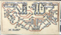
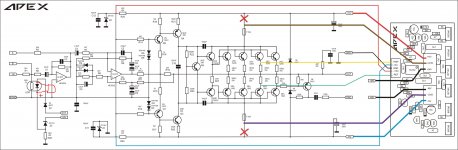
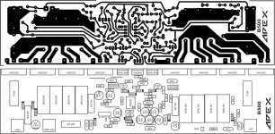
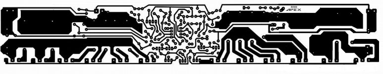
B500 PCB WITH THICKER TRACKS
hi folks here is just a bit modified version of B500 pcb with thicker tracks . Hope u people like it . I wanted to add more o/p pairs atleast 2more pairs but i dont know the size of the current pcb . If any one can tell me the actual length of the pcb it will be very helpfull...
regards
sekhar
hi folks here is just a bit modified version of B500 pcb with thicker tracks . Hope u people like it . I wanted to add more o/p pairs atleast 2more pairs but i dont know the size of the current pcb . If any one can tell me the actual length of the pcb it will be very helpfull...
regards
sekhar
Attachments
hi folks here is just a bit modified version of B500 pcb with thicker tracks . Hope u people like it . I wanted to add more o/p pairs atleast 2more pairs but i dont know the size of the current pcb . If any one can tell me the actual length of the pcb it will be very helpfull...
regards
sekhar
PCB size: 220x52,5mm
Regards
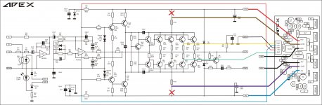
OK guys here is the top layer showing the 2 additional needed jumpers everything else same with the earlier b500 top layer except 2 more pairs and the four 0.33E resistor ........ plz some body print the pcb on a paper and tell me the length............
regards
sekhar
regards
sekhar
Attachments

- Home
- Amplifiers
- Solid State
- 500W PA amplifier with Limiter