mlloyd1 said:I know of at least one manufacturer (who offers VERY long product warranty periods) having a similar circuit (also posted earlier in the thread) installed in products that are famous for reliability. Unfortunately, I no longer have my notes about the particular components and specs for the parts that manufacturer chose to use. Maybe someone who has one or has access to such products could comment or upload some pictures.
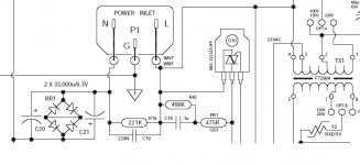
I've attached a snapshot of a schematic from such a well-known manufacturer. They use 33,000uF, 6.3Vdc caps, connected in parallel.
Attachments
Hi,
my suggestion that you measure the actual voltage drops across the caps came over somewhat ambiguously.
The 100% overload and 23 times were numbers plucked from the ether.
I did not try to evaluate this since there was no data to work with.
The Bryston Dc blocker shows inverse // caps with a 1.4 dual diode bypass. The amp manufacturer has used the cap manufacturer's data on acceptable reverse voltage and taken advantage of the 1V to 1.5V reverse quoted by some of them.
I don't think that you must use the normal electrical rules here. The diodes are there to conduct high peak currents. I think they should only be asked to do this relatively rarely. Whether you define rarely as once a second or once a day is subject to argument and should take account of reliability. What is obviuos is that the diodes must not be run at currents or temperatures that could cause them to fail open circuit. That would risk catastrophic failure of the caps, an eventuallity the designer must eliminate from his chosen components.I'm inclined to think of this as a circuit which can support the rated loads of the eletrical devices connected, yes or no.
thanks!
i was also hoping that someone could say exactly what manufacturer and specific part number was used so we could examine specs, too (like ripple current, ESR and temperature ratings, to name a few ...)
mlloyd1
i was also hoping that someone could say exactly what manufacturer and specific part number was used so we could examine specs, too (like ripple current, ESR and temperature ratings, to name a few ...)
mlloyd1
weinstro said:
I've attached a snapshot of a schematic from such a well-known manufacturer. They use 33,000uF, 6.3Vdc caps, connected in parallel.
mlloyd1 said:i was also hoping that someone could say exactly what manufacturer and specific part number was used so we could examine specs, too (like ripple current, ESR and temperature ratings, to name a few ...)
No problem with that.
I took a snapshot from a PDF schematic downloaded from Bryston. It's for a 3B-SST amplifier. Closer inspection reveals that the transformer originally shown is not the power transformer. I've attempted to attach another screen shot.
However, the power transformer does seem to connect through the DC blocker through a varistor. Also, there is a second diode bridge connected to the secondaries of the main transformer, without the capacitors of a dc blocker on page 1 of the schematic. I'm not sure what that is intended to do.
Attachments
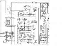
Thanks, weinstro, but the resolution of the schematic is too poor to read the legends.
If it isn't too much trouble, can you scan it at 300 dpi monochrome instead of grayscale?
If it isn't too much trouble, can you scan it at 300 dpi monochrome instead of grayscale?
i'm sorry ...
i guess i wan't clear - i actually meant internal photos of a real unit to see the actual parts used. the schematic downloadable from the bryston site provides a circuit diagram and component values but not much else.
mlloyd1
i guess i wan't clear - i actually meant internal photos of a real unit to see the actual parts used. the schematic downloadable from the bryston site provides a circuit diagram and component values but not much else.
mlloyd1
weinstro said:
No problem with that.
I took a snapshot from a PDF schematic downloaded from Bryston.
...
Hi,
I feel like swearing but I will restrain myself.
Look again at the Bryston layout.
The DC blocker is on the neutral line and there are only two routes for power to get out of the amp.
first exit:- the interference switch suppressor.
second exit:- the DC blocker.
Almost no power will exit through the suppressor which should tell most of you that essentially all the power passes through the DC blocker.
I wish this forum could teach people how to read!
in this case this thread could be of interest:
http://www.diyaudio.com/forums/soli...t-buzzing-toroid-transformers-what-right.html
http://www.diyaudio.com/forums/soli...t-buzzing-toroid-transformers-what-right.html
I've attached a snapshot of a schematic from such a well-known manufacturer. They use 33,000uF, 6.3Vdc caps, connected in parallel.
I believe Bryston use this DC blocker circuit in order to make their Triac inrush current limiter alias power switch to work. DC on the mains can disturb the zero crossing sensing circuit, and can make the triac triggering on the wrong moments. As a bonus it remove DC offset from the line. In Bryston's case it didn't help for transformer humm. I owne several Bryston amps till the 7B's and many of my clients own 4B's and all the (expensive) Plitron transformers have hum in more or less extend.
If people intend to built a DC blocker themselves I strongly advice to simply copy the bryston one with a bridge rectifier, to stay on the safe side.
With kind regards,
Bas
What means for you the term "very old" ??Mr. Tiefbass, did you notice that you picked up an very old thread?
This forum is 10 years old, not 100 years !! Only for computer/EDV stuff 10 years is very old, but not for analog stuff like amps and power supplies - so I think
No problem with that.
I took a snapshot from a PDF schematic downloaded from Bryston. It's for a 3B-SST amplifier. Closer inspection reveals that the transformer originally shown is not the power transformer. I've attempted to attach another screen shot.
However, the power transformer does seem to connect through the DC blocker through a varistor. Also, there is a second diode bridge connected to the secondaries of the main transformer, without the capacitors of a dc blocker on page 1 of the schematic. I'm not sure what that is intended to do.
Please let me know, from which Bryston model you have posted this schematic?
Thank you very much in advance.
This URL is death in the meantime, therefore I will post this pdf here:in this case this AES article is very interesting:
http://www.plitron.com/pdf/AES.pdf
Attachments
-
ACOUSTIC NOISE EMITTED BY POWER TRANSF.I.pdf55.2 KB · Views: 712
-
ACOUSTIC NOISE EMITTED BY POWER TRANSF.II.pdf60 KB · Views: 393
-
ACOUSTIC NOISE EMITTED BY POWER TRANSF.III.pdf59.5 KB · Views: 331
-
ACOUSTIC NOISE EMITTED BY POWER TRANSF.VI.pdf62.6 KB · Views: 303
-
ACOUSTIC NOISE EMITTED BY POWER TRANSF.V.pdf55.3 KB · Views: 323
-
ACOUSTIC NOISE EMITTED BY POWER TRANSF.IV.pdf78.7 KB · Views: 322
-
ACOUSTIC NOISE EMITTED BY POWER TRANSF.VII.pdf71 KB · Views: 348
-
ACOUSTIC NOISE EMITTED BY POWER TRANSF.VIII.pdf49.1 KB · Views: 295
-
ACOUSTIC NOISE EMITTED BY POWER TRANSF.IX.pdf81.4 KB · Views: 312
-
ACOUSTIC NOISE EMITTED BY POWER TRANSF.X.pdf97.5 KB · Views: 350
Last edited:
"Old" means a thread which hasn't got any new posts for quite some time.What means for you the term "very old" ??
This forum is 10 years old, not 100 years !! Only for computer/EDV stuff 10 years is very old, but not for analog stuff like amps and power supplies - so I think
ACOUSTIC NOISE EMITTED BY POWER TRANSFORMER - continuation from post #155
Thank you very much in advance. URL for schemas are follow:
http://bryston.com/BrystonSite05/BrystonDocs.html
The actually question is, what is the better way: to start many small threads or only few threads to the same topic. If it is desired to avoid reviving old threads, the first is the better solution. If it is desired to have all comments together within the same topic, I prefer the second, because in such cases this is the better solution.Mr. Tiefbass, did you notice that you picked up an very old thread? "Old" means a thread which hasn't got any new posts for quite some time.
Please let me know, from which Bryston "MK" editionof model "3BSST" you have posted this schematic sample?No problem with that.
I took a snapshot from a PDF schematic downloaded from Bryston. It's for a 3B-SST amplifier. Closer inspection reveals that the transformer originally shown is not the power transformer. I've attempted to attach another screen shot.
However, the power transformer does seem to connect through the DC blocker through a varistor. Also, there is a second diode bridge connected to the secondaries of the main transformer, without the capacitors of a dc blocker on page 1 of the schematic. I'm not sure what that is intended to do.
Thank you very much in advance. URL for schemas are follow:
http://bryston.com/BrystonSite05/BrystonDocs.html
Attachments
-
ACOUSTIC NOISE EMITTED BY POWER TRANSF.XI.pdf72.1 KB · Views: 255
-
ACOUSTIC NOISE EMITTED BY POWER TRANSF.XII.pdf56.8 KB · Views: 207
-
ACOUSTIC NOISE EMITTED BY POWER TRANSF.XIII.pdf57.4 KB · Views: 214
-
ACOUSTIC NOISE EMITTED BY POWER TRANSF.XVI.pdf64.6 KB · Views: 185
-
ACOUSTIC NOISE EMITTED BY POWER TRANSF.XV.pdf63.7 KB · Views: 191
-
ACOUSTIC NOISE EMITTED BY POWER TRANSF.XIV.pdf81.5 KB · Views: 178
-
ACOUSTIC NOISE EMITTED BY POWER TRANSF.XVII.pdf54.9 KB · Views: 198
-
ACOUSTIC NOISE EMITTED BY POWER TRANSF.XVIII.pdf191 KB · Views: 208
-
ACOUSTIC NOISE EMITTED BY POWER TRANSF.XIX.pdf192.9 KB · Views: 219
Last edited:
DC Filter für 10€
DIY Audio Projects ------ tips and tricks
Two useful links.
I have made this dc filter and now has stopped the noise from the transformers.
DIY Audio Projects ------ tips and tricks
Two useful links.
I have made this dc filter and now has stopped the noise from the transformers.
Attachments
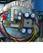
Here you have another DC Blocker this one I use in my mono blocks and this works perfect:
DC-Blocker - Scintilla-buizenversterkers
Rudy
DC-Blocker - Scintilla-buizenversterkers
Rudy
Last edited:
Here you have another DC Blocker this one I use in my mono blocks and this works perfect:
DC-Blocker - Scintilla-buizenversterkers
Rudy
Thank you for posting this topology. Must actually be the royal way and I have never see before in commercial products. The schematic collection, that I know from commercial products, you will find by post #1 about
http://www.diyaudio.com/forums/soli...t-buzzing-toroid-transformers-what-right.html
What is the reason for the choiced polarity of the electrolytic caps (positive pole to anode and negative pole to cathode)? The voltage in the reverse mode is commonly 1V (independend of the voltage values in normal mode).
Last edited:
- Home
- Amplifiers
- Solid State
- DC filter