My last concern about this arrangement is the difference in length between the 2+2 pairs. Two are more twisted than the other. Will there not be a lag in transmission time?
I was curious about this too, so I've just measured the resistance of two pairs in a length of Cat6. I found the difference in resistance to be about 5%, this means signals on the more twisted pairs have 5m more to travel in 100m than on the less twisted ones.
We can assume that the propagation speed is around 0.6c, say 2*10^8 m/s. Your lengths are 10m so the difference will be 0.5m which corresponds to 2.5nS. Sound travels about 330m/s so in 2.5nS it gets less than 1um. Are you going to align your speakers (and your listening position) to this kind of precision?😛
all 4 pairs have a different twist rate. That is to provide some extra rejection between the pairs........I had concerns of running even a line level signal through a pair of 24 Ga over 10 Meters...................
My last concern about this arrangement is the difference in length between the 2+2 pairs. Two are more twisted than the other.
Measure the resistance there and back of a 10m Cat5 pair. Better buy 1000' and cross connect all the ends to allow you to measure all 8000'.
Compare the 20m (10m flow and 10m return) resistance to the source and receive resistances of your equipment.
Andrew, when sending line level signal through CAT5/6.. is it OK to also send 12V trigger signal from processor to amp relay for power activation? Since I have a pair unused out of the 4, thinking of putting it to good use. However I'm not sure of 12V power bleeding onto the other 3 signal pairs..?
Thx
Thx
I've not tried that yet.
The result may depend on how clean the trigger/switch signal is.
Anyone else?
The result may depend on how clean the trigger/switch signal is.
Anyone else?
That makes sense.. as long as the amplitude is not high enough to generate a disrupting filed. I believe max amplitude for relay triggering is 100 mA in my setup.
amplitude is voltage...
Yes its going to be producing 1000x more current then the rca signals.
I got a neat trick, lets just dc offset all the rcas 12volts and cap couple them to amps 🙂
Yes its going to be producing 1000x more current then the rca signals.
I got a neat trick, lets just dc offset all the rcas 12volts and cap couple them to amps 🙂
I have just build a home theater with Turtle Beach 4630 sound card and 5 high efficiency speakers and a diy amp. the amp is made with tda 1521. the room size is 20 sq meter. the speaker is 90 efficiency.
what I want to say is: first you should determine what speaker you need;then calculate the power of the amp. that depend on your room size and the efficiency of the speakers . in this way, i think ,you can pay little money,have a good sound feeling. hope this will help you.
what I want to say is: first you should determine what speaker you need;then calculate the power of the amp. that depend on your room size and the efficiency of the speakers . in this way, i think ,you can pay little money,have a good sound feeling. hope this will help you.
oh, i forget. i don't suggest you build the speakers yourself. a factory made speaker will help you make a shortcut, and cost of little money. espcially the subwoofer.
Member
Joined 2009
Paid Member
I went to the trouble of making a 6-ganged volume control but it turned out not to be necessary. I find that it's sufficient if I have separate stereo volume controls for the front pair, the surround pair and a single one for the centre.
I suggest you use a powered subwoofer, i.e. with a plate amplifier included. Then you are only building 5 channels of amplification inside the box and the requirements on the single transformer power supply will be reduced because arguably the sub is the power hog.
I ended up with a transformer small enough not to meed a slow start circuit coupled with fairly sensitive speakers (89 - 90dB).
Noisy 3ch amps from CAT6 cabling
Hello gentlemen. I posted a couple of entries on here a while back about making dedicated 3 ch amps for my mains and using CAT6 for signal path from an active xover.
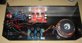
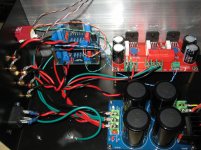
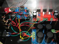
The amps are assembled. With CAT6 cabling hooked up ...TERRIBLE! The twisted pair ends are hooked as they should be to the boards and unhooked on the other. NOISE noise noise. Tried with and without grounding the amp.. no change.
But there's more: I removed the CAT6 input cables and hooked up a standard RCA to a source..... CLEAN as a whistle!
Pics attached. Can someone see something that's not right?!? 😕
Thanks!
Ben
Hello gentlemen. I posted a couple of entries on here a while back about making dedicated 3 ch amps for my mains and using CAT6 for signal path from an active xover.
The amps are assembled. With CAT6 cabling hooked up ...TERRIBLE! The twisted pair ends are hooked as they should be to the boards and unhooked on the other. NOISE noise noise. Tried with and without grounding the amp.. no change.
But there's more: I removed the CAT6 input cables and hooked up a standard RCA to a source..... CLEAN as a whistle!
Pics attached. Can someone see something that's not right?!? 😕
Thanks!
Ben
Attachments
Here is a nice image of optimum ground
courtesy of Douglas Self.
IT makes more sense tor un your speaker ground return to power supply rather than the pc board ground.
courtesy of Douglas Self.
IT makes more sense tor un your speaker ground return to power supply rather than the pc board ground.
Attachments

Last edited:
In my experience that ain't quite the way to do it. Doug Self is fairly well known for measuring rather than listening - if he'd listened to alternatives he might not have made that particular suggestion. The change I suggest is the screen of the input cable should not share a spur with the ground for the feedback network (G). Give each its own ground.
To start of with the ac mains runs virtually the whole length of your enclosure. Could be improved also it is running under the psu board not very safe . also i would sugest you solder the safety earth direct to the iec receptor. what if the push on connecter came a drift and touched the live mains conection. your cable twisting could do with some more twisting and try to keep inputs outputs and dc power in seperate twists and away from each other as much as possible . also where is the mains fuse?????
Nearly there a few things to sort out and you will have a safe working amplifier..
Best Reards Ian. Ps when uncle andrew t see's your amplifier he will hit you with a big stick
Nearly there a few things to sort out and you will have a safe working amplifier..
Best Reards Ian. Ps when uncle andrew t see's your amplifier he will hit you with a big stick
Technically no
You should connect speaker ground return to ground tab on power supply.
But i doubt that your ground loop that is prucing your hum comes from your speaker return. They are probably generated due to your multiple RCA / audio input ground connection points.
You need to have one input ground connection point. The image from Douglas self's book in my first post shows RCA's ground's to connect to star ground.
THAT is why everything goes quiet when you only connect ONE rca , because you have one grounding point. If you connect the multiple input grounds they NEED to all be in one point.
hope my explanation is clear.
look very carefully at the image in my first post.
Power Supply Wiring Guidelines
image 2.2 shows the hysical Connections.
See where speaker return connects to?
image 2.2 shows the hysical Connections.
See where speaker return connects to?
- Status
- Not open for further replies.
- Home
- Amplifiers
- Chip Amps
- 5.1 Channel Chip Amp/Gainclone for Home Theater