Hi Pierre,
I have most of the original bits for a KSA-50 MK2. I have the original Avel Lindberg trafos.
The trafos I have, has two orange wires, 2 pairs of blue and grey, 2 of blue, brown, black and a green/yellow wire.
I guess the green/yellow is for a electrostatic screen. I usually identify the primary by it being thinner gauge wire. For the Avel trafos, they all seem quite thick. So I've measured the inductance, the red to black reads 238mH, red to bown reads 6.3mH, brown to black 163mH. The grey to blue reads over 20H.
Since there are more turns at the primary for a step down trafo, I would guess the blue/grey wires are the primary??
I don't want to get it the wrong way !
Since you have seen the original amp, can you tell me the colour codes or post a photo of the wiring harness ?
Thanks
fs
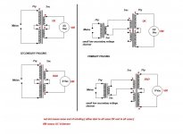
Maybe this help 😉
This is for KSA100mk2 with soft start circuit and two cooling fans, but basically is the same wiring diagram.
Attachments
Hi Neychi,
very useful, exactly what I need. It looks like the primary is connected for 120v, so I'll will need to wire the primaries in series for 240v.
The trafos I have has the blue - grey - blue secondary, but no the higher voltage secondary of the KSA100.
I'm going to wire up the trafo temporarily tonight and so some measuring. I hope I can use 50V caps.
I wonder if the driver board will benefit from local decoupling capacitors? Say 2200uF close to the drivers. Or an inductor to decouple the driver and output section?
I'll get it working first then think about improvements later ;-)
Thanks
fs
Last edited:
More than 100mm. You should add to heatsink (ca 100mm) a fan. So the high can be 140mm.
Hi JKoch,
yes you are right, I forgot about the fan housing mount, thats at least 35mm high.
Thanks
Hi Neychi,
very useful, exactly what I need. It looks like the primary is connected for 120v, so I'll will need to wire the primaries in series for 240v.
The trafos I have has the blue - grey - blue secondary, but no the higher voltage secondary of the KSA100.
I'm going to wire up the trafo temporarily tonight and so some measuring. I hope I can use 50V caps.
...
Do you have a variac or another transformer? Blue/Gray and Violet/Brown is Avel's standard primary color code Transformers and Power Converters From Avel Lindberg, Inc., but it would be a good idea to bring the transformer up at a lower voltage to test. Just feed it 20V or so and look for the proper voltage ratios on the secondary windings.
even if you have a Variac, also use a mains light bulb in the mains live feed.
If the transformer has an internal short or you have wired it wrong then the bulb lights and keeps the voltage across the primary to just a few volts and this allows you time to measure voltages to find out what is wrong.
The easiest error in wiring up a dual primary transformer is to wire one of the windings out of phase. If the mains fuse does not blow quickly, this can very quickly burn out the primary windings. The light bulb prevents damaging currents from flowing. You will not even blow a close rated fuse.
Bob,
good idea with the variac, I bought a secondhand one years ago, but haven't ever used it. It'll be good for testing each stage of the amp, trafo, psu as well.
Thanks
good idea with the variac, I bought a secondhand one years ago, but haven't ever used it. It'll be good for testing each stage of the amp, trafo, psu as well.
Thanks
Great idea Andrew, does the bulb need to be a particular wattage ? I presume a CFL is not good for this application ;-)
The bulb acts like a current limit and will light up if too much current flows?
Is there a good way of determining the phase of the windings ? The thing is sealed in a steel can and epoxied.
The bulb acts like a current limit and will light up if too much current flows?
Is there a good way of determining the phase of the windings ? The thing is sealed in a steel can and epoxied.
there is a bad way to check the phase of the primaries. Plug it in and wait for the fuse to blow!
Much the same applies to multi secondary windings.
Start with a low wattage (40W possibly) incandescent tungsten filament mains bulb.
Build up a mains bulb tester and use it EVERY time, to power up a new or modified project.
Much the same applies to multi secondary windings.
Start with a low wattage (40W possibly) incandescent tungsten filament mains bulb.
Build up a mains bulb tester and use it EVERY time, to power up a new or modified project.
Is there a good way of determining the phase of the windings ? The thing is sealed in a steel can and epoxied.
Hi,
Most undergraduate electronics (analog circuits) textbooks (e.g. Nielsson & Riedel, here in the States) describe a simple method to check the phase of the windings of transformer. If you search on "transformer dot convention", for example, you might find an on-line version of this technique. It involves energizing the primary with a low voltage supply and watching the deflection of the needle of a galvanometer that is attached to one of the secondaries.
I hope that helps.
Ryan
That's odd, I asked that question 5years ago and no Member came back with that answer. I have since seen the question repeated by many other Members and your method is the first I can recall offering a safe solution!!!!It involves energizing the primary with a low voltage supply and watching the deflection of the needle of a galvanometer that is attached to one of the secondaries.
😕
isn't AC voltmeter completely sufficient for that ?
no bulb , no variac , no load ;
if I understood correctly that "problem" is - how to connect 2 secondaries in a way to have one center tapped ?
isn't AC voltmeter completely sufficient for that ?
no bulb , no variac , no load ;
if I understood correctly that "problem" is - how to connect 2 secondaries in a way to have one center tapped ?
and more onerous
How to connect a dual primary transformer to the mains.
source -one small xformer - connected to secondary - will energize primaries , so you can test how to connect them ;
one direction will give XX Vac across two windings together ( I mean - together - in series ) , other connection will give ~0Vac
same for secondaries
connect primaries to mains , measure secs
one way XX Vac , other way ~0Vac
basic things ,knowing them is necessity for safety
if needed - I'll make little sketch later , for both cases
Last edited:
while you are measuring to find Vac or 0Vac, how much current is passing from your LV transformer into your unknown transformer and back again?
Can either of these transformers be damaged while this short circuit current is flowing?
Can either of these transformers be damaged while this short circuit current is flowing?
while you are measuring to find Vac or 0Vac, how much current is passing from your LV transformer into your unknown transformer and back again?
Can either of these transformers be damaged while this short circuit current is flowing?
think ..... or try .
that's kindergarten level .
you can always put resistor between small xformer and xformer under test
Attachments
Update
Hi,
I found some time this evening and did some measuring. I mounted the transformers in the chassis. I used the psu diagram kindly posted by Neychin. The transformer wiring loom is still intact and the jumpers are still insitu which confirms the primary side of things.
With mains ac at 243V, I get 40.3V ....... from one secondary winding! Krell like to run them hot !
I tested the other winding and I got the same result. So 50V caps are out.
40.3 x 1.414 = 56.4V
I should leave at least 10% tolerance, so we are already looking at 61V. The rectifier should drop about 1.4V
So the minimum I should be looking at are 63V caps. I think the original caps were Sprague 40mF 80V devices.
I may use CLC type arrangement, but the first cap will still see 56V ish.
Do you think there will be a problem with back emf ?
Is 63V rated caps still too close to the actual voltage ?
I've used bucking transformer arrangement before successfully. I can drop 6, 12, 15, 24V easily. Do you think that'll be a good thing to do ?
As well as the cap working voltage, I'm thinking about heat dissipation and moving away from the operating point. Although this is what Krell has originally specified for my KSA-50 mk2.....
So from what I've seen, Krell upped the voltage significantly from the original KSA-50 as that had 28VAC x 2 secondaries.
Regards
fs
Last edited:
I told ya 😉
Only the first series of KSA50 (before '83) had lower rail voltage at 36-37V. For KSA50/50mk2 after '83, depending on the year of production and main voltage (220-240V), rail voltage may vary from 45 to 50 V (loaded).
Regards
Only the first series of KSA50 (before '83) had lower rail voltage at 36-37V. For KSA50/50mk2 after '83, depending on the year of production and main voltage (220-240V), rail voltage may vary from 45 to 50 V (loaded).
Regards
Last edited:
Neychi
So far I've managed to read the first 1800 posts of this thread, so yes, you probably did say, but I haven't read it yet ;-)
So far I've managed to read the first 1800 posts of this thread, so yes, you probably did say, but I haven't read it yet ;-)
Firestorm, I meant this 😉
You will need 63V caps. Rail voltage in KSA50 (after '83) and KSA50mk2 was around 48V DC.
Best regards
- Home
- Amplifiers
- Solid State
- Krell KSA 50 PCB