Hi guy's,
I made a small resume of this thread, maybe it can help answer some questions?
Also, there are useful information here (maybe you guy's know already😕)
Regards,
Eric
diyAudio.com Wiki - projects by fanatics, for fanatics
Hi Arick,
the summary is very useful, I have only read 1800 post of the 8000 !
Thanks
fs
Hi,
Did you listen to a KSA-50 before you decided to rebuild an original ?
If not, here's another option:
Build the Krell first with high rails, so you can find out if you like the Krell-sound.
If you don't like it, it's likely that you won't like it fully biased either.
If you DO like it, you can then decide to build it with low rails or keep it as is.
The only increase in cost would be using 63v caps instead of 50v.
Best regards,
Klaas
stop posting this error ridden spreadsheet.Attached is an Excel-worksheet that was posted much earlier in this thread,
to help you calculate the amount of bias vs. ClassA power, generated heat etc.
It is confusing, it mixes up bias currents and total currents and summed currents. It talks about max ClassA voltage- wrong.
Some of it's formulae give the wrong results.
Do not use it.
Go back to the original thread and copy the modified version from Andrew T. that corrects many of the errors and corrects all the erroneous formulae.
Hi Klass,
yes, more than 20 years ago ;-)
Don't know if it was high or low bias, just that it sounded great. I heard it with Quad ESL63 and SMGa.
I managed to source the ironware and major parts for a very good price, so I've decided to go for it. Decent 63V caps are going cost more than what I paid for the case, heatsink and trafos !
I have the driver boards on their way.
Regards
fs
I understand lower impedance load will mean that the amplifier will cross to class B a lot sooner.
Extra : in low impedance loads, the high bias version is thermally relieved, the low quiescent amp will be more thermally loaded.
AKA : a loaded full Class A amp cools down, a high bias amp becomes hotter.
The higher the quiescent current, the more the amp will drive downhill, when loaded by lower impedance loads.
Klaasie

stop posting this error ridden spreadsheet.
It is confusing, it mixes up bias currents and total currents and summed currents. It talks about max ClassA voltage- wrong.
Some of it's formulae give the wrong results.
Do not use it.
Go back to the original thread and copy the modified version from Andrew T. that corrects many of the errors and corrects all the erroneous formulae.
Hi Andrew,
any chance you got the spreadsheet handy - or the approximate post number ? I haven't come across it yet. I've got up to post 1800 ... out of 8200
Thanks
fs
wrong.KSA50 is modestly rated as an 50W amplifier to maintain doubling output power at lower impedances:
50W/8ohm
100W/4ohm
200W/2ohm
400W/1ohm
The KSA50 does not double it's output each time the test resistor load is halved.
The 50W/8ohm is the rated ClassA maximum into an 8r0 resistor load.
The 100W/4ohm is the rated ClassAB maximum into a 4r0 resistor load.
The 200W/2ohm is the stated ClassAB maximum power into a 2r0 resistor load, when certain operations conditions are met, i.e. higher mains input voltage.
The 400W/1ohm is a figment of someone's imagination. I can guarantee that it is not possible using the methods used to obtain the 50W and 100W figures which are achievable.
your existing transformer will not allow you to bias the rebuilt 2pair output stage to 1.9A.To be honest, I don't mind if I have more or less class a power,..........................Also it is my understanding that when an AB class amplifier crosses, it produces more distortion than a class b amp. That is my rationale for optimising the class a power.
Do not change the voltage of your transformer. If you retain the same wire diameters you are restricted to the same maximum currents.
Accept what you have or buy again.
You will need to use lower bias to suit the higher voltage.
You can build a very good ClassAB amplifier, but we need to clear up a few misconceptions.
ClassB produces lot's of crossover distortion. It sounds bad! Do not make any comparisons to ClassB. Just to confuse things more, D.Self uses "his ClassB" definition to mean optimally biased ClassAB.
ClassAB can be under biased, or optimally biased, or over biased.
ClassA is biased to suit it's maximum rated ClassA output current.
Under biased ClassAB is not nice, it produces crossover distortion that is quite obvious and as temperatures move around during music reproduction, this biasing varies causing variable amounts of crossover distortion. Cordell calls this dynamic crossover distortion and it applies to all amps that operate in ClassAB during part of their output range.
Over biased Class AB is not as bad as under biased, it is more listenable. The effects of temperature variations are not as bad as under biased. Many manufacturers bias their amps this way and call it high biased ClassAB (the high voltage KSA50 falls into this category).
Now to optimally biased ClassAB (=D.Self ClassB). Here the output stage is set up to minimise the amplification changes that occur at crossover and thus minimise the distortion due to crossing that region. These amplifiers are set up using voltage instead of current. Set them by adjusting to the recommended Vre, usually in the range 15mVre to 26mVre.
The distortion from an optimally biased ClassAB amplifier is lower than all the other ClassAB and ClassB biasing methods.
The transition from ClassA (very low output current) to ClassAB ( medium and high output currents) is clean and almost inaudible.
ClassA avoids the transition from ClassA to ClassAB and thus avoids crossover distortion.
However push/pull ClassA can transition to ClassAB, if the demanded current is more than the maximum ClassA current capability. To minimise the sound effect of this transition one must go from optimally biased ClassAB in the ClassA region to the ClassAB region.
If the output stage is designed to have a very high optimal bias then it works in ClassA for much of it's time and when asked to transition to ClassAB (high current transients) it does so with minimal crossover distortion.
A 2pair KSA50 on high voltage could be set to optimal ClassAB bias to get the benefit of avoiding much of the crossover distortion sound effects, but 2pair limits just how much ClassA current is available.
A KSA100 4pair output stage gives more freedom to adopt this bias philosophy.
Here's my examples.
adopt Re=0r68, 2pair mj15003/4, 25mVre
Bias current = 73.5mA, Maximum ClassA current = 147mA
adopt Re=0r1, 2pair mj15003/4, 19mVre
Bias current = 380mA, Maximum ClassA current = 760mA
adopt Re=0r1, 4pair mj15003/4, 19mVre
Bias current = 760mA, Maximum ClassA current = 1520mA
adopt Re=0r1, 6pair mjl4281/4301, 19mVre
Bias current = 1140mA, Maximum ClassA current = 2280mA
That 2280mApk allows ~41W of ClassA into 8r0.
I see this philosophy as having your cake and being allowed to eat it.
Much to think about, particularly considering that Re can be experimented with after assembly.
Last edited:
wrong.
The KSA50 does not double it's output each time the test resistor load is halved.
The 50W/8ohm is the rated ClassA maximum into an 8r0 resistor load.
The 100W/4ohm is the rated ClassAB maximum into a 4r0 resistor load.
The 200W/2ohm is the stated ClassAB maximum power into a 2r0 resistor load, when certain operations conditions are met, i.e. higher mains input voltage.
The 400W/1ohm is a figment of someone's imagination. I can guarantee that it is not possible using the methods used to obtain the 50W and 100W figures which are achievable.
As you can see, paper can handle anything...
even 500V/us slew rate😀
Attachments
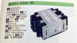
What has KSA80 got to do with KSA50 ratings?
Note also that KSA80 omits a 1r0 rating.
Absolutely nothing...
I have found somewhere this information about KSA50 output power so I put this as a comparison.
Hi firestorm. what about of these:
2 KENDEIL 63V 22000UF CAPACITOR KRELL KSA50 NAIM HICAP! - eBay (item 180571547467 end time Dec-06-10 15:11:09 PST)
but they are going to run at nearly $300. if you go for 8 of them to get 44000uF per rail
IF i was you
I would sell the two toroidals you have on ebay or here in the swap forum.
And get two of these:
Nuvotem | Transformers | Transformers | Toroid Transformers | Toroidal 230Vac Primary 15VA to 1000VA |0500P1-2-030 (you can even opt of the 25V AC 500va ones for less heat and slightly less output wattage)
And then get 4 x 50V capacitors.
Good luck on deciding
your existing transformer will not allow you to bias the rebuilt 2pair output stage to 1.9A.
Do not change the voltage of your transformer. If you retain the same wire diameters you are restricted to the same maximum currents.
Accept what you have or buy again.
You will need to use lower bias to suit the higher voltage.
You can build a very good ClassAB amplifier, but we need to clear up a few misconceptions.
ClassB produces lot's of crossover distortion. It sounds bad! Do not make any comparisons to ClassB. Just to confuse things more, D.Self uses "his ClassB" definition to mean optimally biased ClassAB.
ClassAB can be under biased, or optimally biased, or over biased.
ClassA is biased to suit it's maximum rated ClassA output current.
Under biased ClassAB is not nice, it produces crossover distortion that is quite obvious and as temperatures move around during music reproduction, this biasing varies causing variable amounts of crossover distortion. Cordell calls this dynamic crossover distortion and it applies to all amps that operate in ClassAB during part of their output range.
Over biased Class AB is not as bad as under biased, it is more listenable. The effects of temperature variations are not as bad as under biased. Many manufacturers bias their amps this way and call it high biased ClassAB (the high voltage KSA50 falls into this category).
Now to optimally biased ClassAB (=D.Self ClassB). Here the output stage is set up to minimise the amplification changes that occur at crossover and thus minimise the distortion due to crossing that region. These amplifiers are set up using voltage instead of current. Set them by adjusting to the recommended Vre, usually in the range 15mVre to 26mVre.
The distortion from an optimally biased ClassAB amplifier is lower than all the other ClassAB and ClassB biasing methods.
The transition from ClassA (very low output current) to ClassAB ( medium and high output currents) is clean and almost inaudible.
ClassA avoids the transition from ClassA to ClassAB and thus avoids crossover distortion.
However push/pull ClassA can transition to ClassAB, if the demanded current is more than the maximum ClassA current capability. To minimise the sound effect of this transition one must go from optimally biased ClassAB in the ClassA region to the ClassAB region.
If the output stage is designed to have a very high optimal bias then it works in ClassA for much of it's time and when asked to transition to ClassAB (high current transients) it does so with minimal crossover distortion.
A 2pair KSA50 on high voltage could be set to optimal ClassAB bias to get the benefit of avoiding much of the crossover distortion sound effects, but 2pair limits just how much ClassA current is available.
A KSA100 4pair output stage gives more freedom to adopt this bias philosophy.
Here's my examples.
adopt Re=0r68, 2pair mj15003/4, 25mVre
Bias current = 73.5mA, Maximum ClassA current = 147mA
adopt Re=0r1, 2pair mj15003/4, 19mVre
Bias current = 380mA, Maximum ClassA current = 760mA
adopt Re=0r1, 4pair mj15003/4, 19mVre
Bias current = 760mA, Maximum ClassA current = 1520mA
adopt Re=0r1, 6pair mjl4281/4301, 19mVre
Bias current = 1140mA, Maximum ClassA current = 2280mA
That 2280mApk allows ~41W of ClassA into 8r0.
I see this philosophy as having your cake and being allowed to eat it.
Much to think about, particularly considering that Re can be experimented with after assembly.
Hmm,
Looks like my understanding of amp class is lacking. I need to go back and read the D Self's and B Cordell's books.
If I do lower the rail voltages, from 50V to 38V DC. I should be able to bias it the output stage to 1.9A?? I may have sacrificed some of the ultimate AB power, but I would still expect to get 50W class A from a 400VA trafo ? Even accounting for transformer derating because of cap input.
If I go with your calculations, the KSA-50.2 I have bought would only ever give 13.5W class A @ 8R ? After that it would transition into AB? So if I have 4R speakers, then it would be hald of that ? 6W ? thats what I would expect from a 300B SET 😕
I'm more confused now, than when I first started looking into this !
Cheers
fs
Tangmoster
I need to get a good understanding of this monster before I spend any more money on parts.
Thanks for the suggestions,
fs
I need to get a good understanding of this monster before I spend any more money on parts.
Thanks for the suggestions,
fs
I'm more confused now, than when I first started looking into this !
More fuel : some Class A designs are biased for full continuous output power in 4 Ohm, familiars ; Marky Lev ML2 (25W) and the K.Lang (20W) design.
My 2cents...
Tune the C on the CLC to +/-38VDC and move forward. You will stay truer to the original design with a cleaner power supply. That first C on CLC should end up being a 1UF to 10UF cap, and you can model it on the free PSUDesigner from Duncanamps.com to target a value.
Otherwise you will second guess yourself to the point of just giving up.
Big oops, looks like i pulled that one from my 'archives' a bit too fast.stop posting this error ridden spreadsheet.
It is confusing, it mixes up bias currents and total currents and summed currents. It talks about max ClassA voltage- wrong.
Some of it's formulae give the wrong results.
Do not use it.
Go back to the original thread and copy the modified version from Andrew T. that corrects many of the errors and corrects all the erroneous formulae.
Thanks for pointing out my error AndrewT,
it seems i've run out of editing-time to delete the attachment 😱
Looks like we're much in the same boat wrt knowledge of amplifier classes.Hmm,
Looks like my understanding of amp class is lacking. I need to go back and read the D Self's and B Cordell's books.
If I do lower the rail voltages, from 50V to 38V DC. I should be able to bias it the output stage to 1.9A?? I may have sacrificed some of the ultimate AB power, but I would still expect to get 50W class A from a 400VA trafo ? Even accounting for transformer derating because of cap input.
If I go with your calculations, the KSA-50.2 I have bought would only ever give 13.5W class A @ 8R ? After that it would transition into AB? So if I have 4R speakers, then it would be hald of that ? 6W ? thats what I would expect from a 300B SET 😕
I'm more confused now, than when I first started looking into this !
Cheers
fs
Does a 300B SET deliver >> 50watts ClassAB in 8r ?
And quadruple this output into 2r? I don't think so
Stormy day @ the beach, isn't it Jacco 😀
Linkjegenerous bottom
Hi AndrewT,
can you point me in the direction of the corrected class a spreadsheet ? I have used the search function and I've looked at the wiki, but I can't find it.
Thanks
fs
can you point me in the direction of the corrected class a spreadsheet ? I have used the search function and I've looked at the wiki, but I can't find it.
Thanks
fs
My 2cents...
Tune the C on the CLC to +/-38VDC and move forward. You will stay truer to the original design with a cleaner power supply. That first C on CLC should end up being a 1UF to 10UF cap, and you can model it on the free PSUDesigner from Duncanamps.com to target a value.
Otherwise you will second guess yourself to the point of just giving up.
I've been playing with the psu designer, very interesting.
I'm going to work out the total current requirement first, so I can put in a realistic Rload value.
I seem to be going in circles with this. I guess you guys have seen it and been there 5 years ago 😛
- Home
- Amplifiers
- Solid State
- Krell KSA 50 PCB