All you would have to do to change from 39 to 50VDC is change that first cap of the CLC from 1 - 10uf to over 1000uf and your there. Make sure the rest of you caps are good for the higher voltage.
Try it on psudesigner. You can dial in your voltage from .9VAC to 1.414VAC changing that first cap. Additional RC can be added after that initial CLC
Try it on psudesigner. You can dial in your voltage from .9VAC to 1.414VAC changing that first cap. Additional RC can be added after that initial CLC
Last edited:
I've had some very strange results from psu designer. With just LC, I get really high voltage (2KV) between the rectifier and L, back emf ?
Also a Csmall - L - Clarge, 10u - 10mH - 47mF . voltage at 10u varies from -27V to +66V
The leading C will need to be rated quite high, but the negative voltage doesn;t seem right though.
Also a Csmall - L - Clarge, 10u - 10mH - 47mF . voltage at 10u varies from -27V to +66V
The leading C will need to be rated quite high, but the negative voltage doesn;t seem right though.
Yes I have found the prog a little buggy. I notice that if I change too many parameters the programs gives goofy results. I always start a brand new model and get realistic results again.
Hi all,
Courtesy of Jozua, I removed the board of his original KSA50 Mk2 (fan is bottom-mounted) for some much-needed restoration and tweaking. While busy I thought I'd reverse-engineer the circuit diagram since there are so many KSA50 diagrams and variations floating around. Attached is a picture of the removed board.
What I've found is that the diagram is identical to a hand-drawn one posted somewhere in the thread in 2004 or 2005, which I reattach for convenience. Besides the different transistors, the differences to the clone are minor. The only part differences are the feedback resistors, which are 12k1 and 475R instead of 22k and 1k5, leading to a gain of 28.5dB compared to 24dB. The rest of the diagram and resistor & capacitor values are the same.
Another difference is much higher power rails, at 50V loaded, 52V unloaded. This choice of higher rails could perhaps be due to the higher gain.
As you can see the board's negative section has seen some extensive trauma & prior repair, and the white 2.2uF capacitor at the bottom along with the two tack-soldered resistors are a DC-blocking RC filter at the input. Whether this was a private mod or an afterthought from Krell I'm not sure - on the KSA100Mk2 there also is a tack-soldered capacitor at the bottom of the board so it's not unprecedented.
Adam, I built Jozua's clone with a combination of Dale, Holco and Riken resistors, with using the Rikens and Holcos for the critical parts and Dale for the rest. Boards were the original Delta Audio ones; I believe the Pinkmouse version (which I also built but never got round to test) should perform better. The feedback cap was a single 1000uF 16V Black Gate NX. Wire was van den Hul for speaker and interconnect, Kimber for sigal hookup and generic stuff for power. Caps were 68,000uF Alcan types (cheap). The intention was for it to be upgradeable to a KSA100, with 4 pairs output devices on 2 separate heat tunnels, making it run very cool since the bias is half what the heatsinks can handle. I attach two low-res pictures I took during assembly in 2005.
Regards,
Pierre
Hi Jozua/ Pierre,
the circuit diagram you attached shows the two caps as 390pF.
I believe that it was concluded that the value should be 39 or 47pF. Can you please confirm what the correct value is on the original board? Thanks.
Hi, I’m probably going to look stupid here but I’m relatively new to electronics in general.
I’ve been looking at starting an amplifier project and reading through this thread with interest.
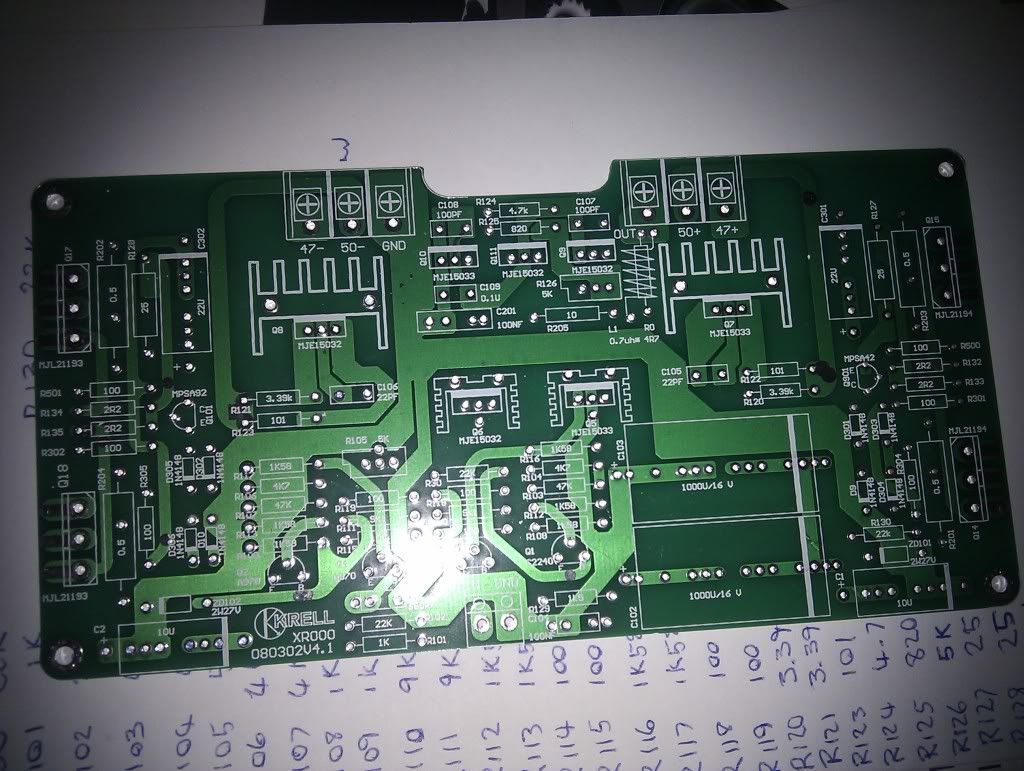
Could someone please explain why the KSA50 based boards from tubeshunter on eBay have +/- 47v and +/-50v?
Thanks,
Charlie

I’ve been looking at starting an amplifier project and reading through this thread with interest.
Could someone please explain why the KSA50 based boards from tubeshunter on eBay have +/- 47v and +/-50v?
Thanks,
Charlie
Probably because they are not KSA50 PCBs.
They might be copies of clones of a particular version of the KSA50.
They might be copies of clones of a particular version of the KSA50.
Perhaps a higher voltage for driver stage and lower for output stage ? Like the KSA-100?
Have you bought them ?
Did you get a circuit diagram?
Have you bought them ?
Did you get a circuit diagram?
Last edited:
Hi, yes I have bought them, but I haven’t received them yet. Any opinions on giving them a go or should I just sell them on and buy something better? What would be the best way to go about providing the two different voltages?
I’ll let you know what they come with when I get them.
Thanks,
Charlie
I’ll let you know what they come with when I get them.
Thanks,
Charlie
If you want a real ClassA amplifier and have heatsink/s big enough to dissipate all that ClassA power, then go and read the KSA50 clone thread.
All the information and more is in there.
All the information and more is in there.
Thanks, I’ve read through most of it over the last few days including the wiki and picked up a lot of tips but I guess my basic knowledge is still lacking, I think I’m capable and I would like to have a go at this amp but I have a lot to learn. I won’t be starting it any time soon, lots of research to do before I start building anything. How would I go about creating a power supply with the two voltages needed? Everything I’ve read so far concentrates on just one voltage.
Do you mean two transformers per channel (33v and 35v)? Or one for each stage of both channels?
WOW! Keep this thread goin all... I haven't been around in a while.... busy with D-Cinema and all but I was amazed to see it here on page one of today's threads... Mine is still running just fine after all this time.
Mark
Mark
Glad to hear it, hopefully I'll have a working one in a few months. Anyone have anything to say about the boards I posted?
Sent from my HTC Desire using Tapatalk
Sent from my HTC Desire using Tapatalk
How would I go about creating a power supply with the two voltages needed?
For a mere 3 Volts difference chances are you don't need 2 different voltages at all; likely that only the frontend runs a little higher to allow the outputs closest swing to the rails (maximum output).
Especially bipolar outputs don't really need that as they swing to within 1 V of the rails; only a noticable issue for mosfet outputs with their 3-4 V turn on VGS.
When you got the schematic one could check for sure.
Thanks I was thinking the difference of 3v probably wouldn’t matter too much, probably bigger fluctuations in the mains in my house, lights go dim for a few seconds sometimes and power cuts happen all the time! Hopefully they will come with schematics and more info.
hi all,
merry christmas,
where can i have the pcb for the krell ksa 50 and 100.
thanks
happy listening
abes
merry christmas,
where can i have the pcb for the krell ksa 50 and 100.
thanks
happy listening
abes
Hi, the Chinese boards arrived today, they look quite good quality but they didn’t have anything with them, not even a packing note. I’ve emailed the seller to see if they have any more info and a schematic.
I’ve been trying to make a parts list and comparing it to the boards in this thread, seem quite a bit different, might give them a go anyway though.
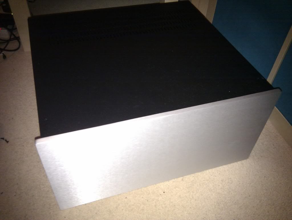
Modushop.biz case also arrived today, looks lovely!
I’ve been trying to make a parts list and comparing it to the boards in this thread, seem quite a bit different, might give them a go anyway though.
Modushop.biz case also arrived today, looks lovely!
- Home
- Amplifiers
- Solid State
- Krell KSA 50 PCB