Resin source
Does anyone have a source for the special resin used for potting the transformers?
Does anyone have a source for the special resin used for potting the transformers?
This shows that perhaps they were onto something when stating 'high current' causes vibration to feed back into the input stage, thus adding to smearing and lessened sound quality. It does not necessarily mean they were skimping on the build quality.
They were onto something when one of the engineers said "Don't worry about the extra vibration from using a smaller tranformer. We can pot it and decouple everything from the chassis"
The accountant said "Good work guys we won't have to sack/fire you after all"
Why did they not just put the power supply in another box
Exactly. For the money you would expect nothing less.
Last edited:
They were onto something when one of the engineers said "Don't worry about the extra vibration from using a smaller tranformer. We can pot it and decouple everything from the chassis"
The accountant said "Good work guys we won't have to sack/fire you after all"
Are you serious or just playing around?
So you are saying having to manually pot tansformers (instead of just using a bigger size), then attach them directly to the feet, suspended from the chassis with teflon insulators, with all that hassle involved, is an accounting driven move designed to save money?
Goldmund's 'mechanical grounding' sound like a laborious and costly process that would not have been done it it did not give sonic benefits.
Mind you, there are plenty of auidiophile manufacturers that have stupidly expensive design philosophies that don't actually sound very good. But at least Goldmund's older amps do have a reputation for being the best out there.
Why did they not just put the power supply in another box and you place it in the house next door, or pot the whole damn thing.
I have some early Meridian amps, that are 3 box setup. 2 boxes for each channels transformer, the 3rd box housing the circuitry.
Hello
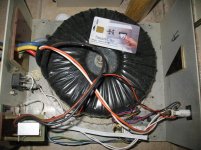
Mostly I'll build my amps two separate boxes.
1 box just for the transformer . I use industrial copper connector .
You can imagine a 1.5KVA transformer will have mechanical noise,vibration etc even if is a low noise type.
Sorry my transformer bit dusty..
The same transformer I can use to power up another amp to .
But to save on the size of the transformer it sound stupid, after spend a lot of money to isolate the noise..😕 They want to save on copper or the Global warming stupidity already everywhere???
Save on energy 10C ?
Of course the people who buy their amps will pay for the extra work etc.😛
Greetings
Attachments

BOM list
Goldmund BPM list
A BOM list for the main board I have found in post 490
A Bom list for the security board I have not seen so far. Do you have Alex???
In the BOM-list the capacitors (e-lyt) are all 100 V types. 100 V types are hard to be found.
Which one of this could be lower than 100 V without security problems (not from a quality point of view). It is a lot of quality capacitors (Elna, Phillips...) for reasonible prices out there.
I have on my hands four 12000uF/80 for C31/34. With a +/- 60 V transformer, will that be ok??
Can anyone point out a minimum volt-range for all the capacitors (e-lyt)
Eivind Stillingen
PCB board 31...
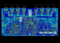
... I have changes in placing final transistors and connectors , in general what was sugested and I hoppe this time will be better than the last one .Schematic will be updated with new values of devices .
Alex .🙂
... I have changes in placing final transistors and connectors , in general what was sugested and I hoppe this time will be better than the last one .Schematic will be updated with new values of devices .
Alex .🙂
Attachments

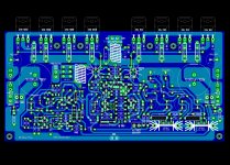
This thread has taken a turn for the better, some modification here is turning it into a better amp. Alex this is a beautiful layout. If I may ask a question, why is the front end power supply fed through a decoupling cap. Is it intended as a high pass filter?
As I said this thread has actually taken notice and done something, also it got source resistors. This is already better than the Goldmund amp, I am waiting for Alex's post of the schematic and it will become clear. I would like to see the front end voltage increase a little that would improve the output swing to near rails since they have the extra MOSFET.
Why 4 output transistors instead of 3?
The internals of the J162/K1058 may be the same, but the thermal resistance of the TO-3P package is not identical to a metal case TO-3.
Makes it the equivalent of a lower power TO-3 original, the same power handling level requires either more devices, or significantly larger heatsinks.
Adding 2 power MOSFETs is cheaper, one third more peak current comes as a freebee.
Does require a little more driver quiescent current (not a third more) to meet the original specs.
Elementary.
@alex mm:
How is GND partitioned on your PCB? I see some partitioning but to me it doesn't make sense at all. GND is mostly daisy chain connected. Some decoupling caps are connected to the plane, some to the daisy chain ground. What is the concept?
Why do you use jumpers on a 2 layer PCB but remove plane fill underneath the jumpers?
Do you use thermal relief for pads connected to planes?
Regards,
Lee
It doesn't matter is the board has 3 pairs of MOSFES, or 4 pairs. This just gives more options for potential builder. If you only want 3 pairs, as in the original schematic, simply don't mount the 4th pair. That is what I'm planning on doing. Also, the source resistors are a complete waste of space, but again, this gives more options for the stubborn people who don't understand the original schematic and want to include them. Those who want to build it like in the original schematic (myself included) just install jumpers instead of the resistors. I like that this board gives many options, this should satisfy a lot of people and we can have many builders participate.
Alex, the board looks very good! My only concern is this: Is there any way that you can please make it so that the -120VDC is connected to the -120VDC in the power supply? And also +120VDC is connected to the +120VDC in the power supply? Otherwise we will have to run jumpers, or wires and it's just not as good, nor clean looking.
Same goes for the protections circuit's +/- 80VDC and 60VAC. Those should also be already connected, otherwise lots of jumpers and wires will have to be run. I really don't like to run hat many jumpers/wires on a circuit board. If it's already connected it just makes it so much cleaner and probably better performance wise as well.
If you could please make those changes, the board will be ready for the group buy in my opinion.
Thermal relief pads should be used as that makes soldering easier. As for the grounding scheme, it makes no difference to me. All ground points in the entire schematic should be connected to the ground plane as in all original Goldmund amplifiers.
PCB ....board 32
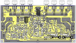
..... @Lee Knatta ground plaine connect smal devices like resistors , capacitors ,transistors and daisy chain power gnd like elyt capacitor and large 10.000uF/100v . I whish to draw an universal board to be avaible also like single side board for home made .I can not afford to buy me a circuit so as to make it home.Another PCB picture attached .
Alex .😀
Attachments
- Home
- Amplifiers
- Solid State
- The Very Best Amplifier I Have Ever Heard!!!!