Thank you,DF96,for the further details; the output triodes have a mu of about 2 and perhaps this begins to explain what I am hearing.
Minor correction: the capacitor value needs to be adjusted by mu+1, not mu. Sorry! In most cases these are the same, within component tolerances, but for mu=2 there is a 50% difference. So your 20uF cap, which looks like 40uF at each cathode, will look like 13uF in series with each anode. The 100H primary will be damped by both the anode impedance and the reflected speaker load via the secondary, but you can expect to see something interesting happening around 4-5Hz. Oops - record warps! If 100H is the total P-P primary then each half will see less inductance so higher frequency but you will still be in the region of arm-cartridge resonance.
Of course, if you put in a bigger capacitor you could find problems down in the 0.1-1Hz region of mains voltage variations, but the anode impedance would offer better damping.
I must say you have set me thinking - I have not considered before the interaction between cathode bypass capacitor and OPT primary inductance. For conventional resistor cathode bias the whole thing is reasonably well damped so nasties are less likely. It seems that CCS bias, like other 'simple' circuit changes, opens up new challenges.
I have always assumed that it would be necessary to take this into consideration with parallel-feed output as well(although I have not yet tried this output structure).
I mean the blocking cap,of course, in this case, assuming grid bias.
I mean the blocking cap,of course, in this case, assuming grid bias.
Last edited:
I have done some simulations, for lowish mu triode and UL pentode. The circuits are my attempt to model what the anode sees, for these two outputs using either resistor bias ('k' version) or CCS bias. For the triode I assumed an effective C at the anode of 10uF, for the UL 1uF (bigger C, but bigger mu too).
You can see that the low mu triode with CCS has an LF peak of 4dB around 8Hz. Using resistor bias changes it to a 0.6dB peak around 12Hz.
The UL output is smoother, with or without CCS. This is because the higher anode impedance damps the peak away to nothing.
You can see that the low mu triode with CCS has an LF peak of 4dB around 8Hz. Using resistor bias changes it to a 0.6dB peak around 12Hz.
The UL output is smoother, with or without CCS. This is because the higher anode impedance damps the peak away to nothing.
Attachments
I would still be upping your capacitance, a simple back to back arrangement would be worth a try and I would be more than interested in your impressions.
Shoog
Shoog
Yes Shoog;
I will definitely be trying your scheme in the next iteration of this topology; this amp was only an experiment which I really did not expect to work so well. It is therefore built in a box 280 x 190 x90(!) and the power supply the same. I have suitable caps but there is absolutely no chance of fitting them in. Unfortunately I have my students breathing down my neck at the moment and I must learn quickly Prokofieff Piano sonata no. 8 which is about a half hour long and pretty challenging-so no chance to build anything for a few weeks. At half term I hope to build the mic amp we discussed and then I hope the next scaled up power differential at Christmas time-I am planning to use 6S41S this time so that I can use the toroids with 9V secondaries rather than the 6V ones I used with 6S19P. In January I begin a very substantial applied maths module to prepare me for the level 3 topics of my physics degree, so, it's all go! I think I remember reading in one of your posts that you are studying too?
Best wishes, N.A.
Hey Shoog,
Just outa curiousity , what output tubes and format (pentode/triode tied/UL) are you running ?
What is your driver and associated topology ?
A schematic perhaps , if this isn't asking too much ?
.......................Blake
Just outa curiousity , what output tubes and format (pentode/triode tied/UL) are you running ?
What is your driver and associated topology ?
A schematic perhaps , if this isn't asking too much ?
.......................Blake
I've been following this thread closely also and find it fascinating. I did some research and came up with the thread where Shoog dialed in the topology he needed to get balanced currents on both sides of the PP.
http://www.diyaudio.com/forums/tubes-valves/98788-any-comment-vacuum-state-dpa300b-2.html
Brian Beck's contribution there was very, very useful. I have a toroidal output transformer also that's just dying to be put to use. It's a monster from Mr. Vanderveen with a cathode feedback winding built into it. I plan to not use global NF so perhaps the oscillation problem would be moot. But I'd like to use the extra cathode feedback winding to increase the damping on the final stage in lieu of that absense. Is it possible to still use tha winding in combination with schematic E in the drawing Brian Beck made in that thread? I think that is the one you have all concentrated on. Thanks much.
If it doesn't work I might go to Schade feedback on the final stage. Ya gotta do something in exchange for no GNF.
Thanks for finding that ancient thread. I have stopped giving my thanks to Brian but he deserves all the credit for the original idea. That amp idea is where it all started, but I have moved on from there considerably since then.
This is what I am currently listening to which is a considerable step up from the original in terms of bass punch and top end extension.
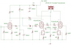
The second schematic is a version of the Simple EL84 amp. This works really well, but I had to reduce the plate load on the 6AU6 to fill out the sound a bit.
The bass is not as tight as the 6080 amp - but that is to be expected considering the difference in output impedance.
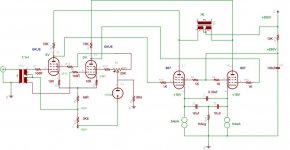
The next one is my version of the Tabor amp by Gary Pimm. This sounds the least satisfactory of the lot. Don't quite know why. I feel if I ran it Triode strapped it would probably sweeten up. The surprising thing is that running this amp Pentode should have lower output impedance than triode. Still I think the 807 is a reasonably high distortion pentode.
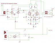
i also built a PP headphone amp using ECL82's. Sounds sublime and would make a perfectly workable power amp for speakers.
This is what I am currently listening to which is a considerable step up from the original in terms of bass punch and top end extension.
The second schematic is a version of the Simple EL84 amp. This works really well, but I had to reduce the plate load on the 6AU6 to fill out the sound a bit.
The bass is not as tight as the 6080 amp - but that is to be expected considering the difference in output impedance.
The next one is my version of the Tabor amp by Gary Pimm. This sounds the least satisfactory of the lot. Don't quite know why. I feel if I ran it Triode strapped it would probably sweeten up. The surprising thing is that running this amp Pentode should have lower output impedance than triode. Still I think the 807 is a reasonably high distortion pentode.
i also built a PP headphone amp using ECL82's. Sounds sublime and would make a perfectly workable power amp for speakers.
Attachments
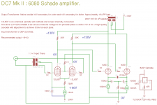
Funny thing; I originally saw these power toroidals used in a design on Steve Bench's site and as far as I remember there were no current sinks or any unusual measures to match currents. I myself have always used differential topology simply because my first two builds,forced on me by the circumstances of a commercial unit failing during a recording session, were mic amps that had to be used in a non ideal environment so I thought I had better make them as immune to interference as possible.I had not yet even built from scratch a common cathode stage! I got lucky,it worked first time, I got used to the topology and certainly there seemed no reason not to use it from then on. My balanced variable EQ phono amp is a ridiculous beast with a separate choke input PSU for each stage and my line stage is balanced cathode followers on pentode current sinks. My most recent experience of only a month now is that power toroids with differential low mu,low impedance triodes is a tremendous combination. Shoog encouraged me to finish it off as I had my doubts(I thought such an inexpensive part would be bound to be compromised) and I would strongly advise anyone to try it-no matter what exotic equiptment they are used to.
Yes,
I think there are many advantages to this topology using cheap toroids. Obviously if you are using 6as7's you will get better damping since it has such low mu. Schade feedback on top of that is iceing on the proverbial cake. So it works well with pentodes giving a lot of signal amplification. (You need a lot with just one stage of voltage amplification driving 6as7.)
I'm going in a bit of a different direction with my next build. John Broskie discussed a differential version of the aikido with the differential stage at the cathode followers instead of at the voltage amplification stage. It intrigued me and I think I might try that just to try it. It has one big drawback in that you can't just ground one input grid to drive it from unbalanced signal sources. However my preamp has a balanced output so I can live with it.
Since I'm a bit of a newbie to building amps I really should start out small, complication wise (not soundwise) and do a 6as7 version like Shoog's. It's simple and has less to go wrong. I might save the big plitron (660 H primary inductance!) for the version driven by the differential aikido and do it later. You guys are starting to convince me.
BTW, I don't think the cathode feedback winding instead of Schade feedback would present a problem. I haven't simmed it yet but it seems to me one could just fit them back to back between the big 'lytics. You'd then want to parallel with 2 bypass caps instead of just one, then grounding everything through the 1 meg resistor where everything ties together. That way the cathode feedback windings would also be using the bypassing caps as well as the big ones.
Best,
660H- Wow!
I think you will find it impossible to do it in 2 stages with low mu triodes-mine only works because my preamp puts out more than 5 volts. Why not 3 stages? Also, why not try a tube no-one has tried yet. I wonder what S11E12 would be like triode connected with this topology.It looks quite cool...
I think you will find it impossible to do it in 2 stages with low mu triodes-mine only works because my preamp puts out more than 5 volts. Why not 3 stages? Also, why not try a tube no-one has tried yet. I wonder what S11E12 would be like triode connected with this topology.It looks quite cool...
660H- Wow!
I think you will find it impossible to do it in 2 stages with low mu triodes-mine only works because my preamp puts out more than 5 volts. Why not 3 stages? Also, why not try a tube no-one has tried yet. I wonder what S11E12 would be like triode connected with this topology.It looks quite cool...
Mine puts out over 5 volts too. If I built one along the lines of Shoog's 6as7 I wouldn't use that OPT because it has 2000 ohms primary impedance into 5 ohm speakers. I'd probably use the one he has used or something close. I'm thinking paralleling 2 6as7 per channel and maybe driving them with one stage of el84s differentially. They have an mu of 20 and I've heard some good things if they are used in that position. The problem might be in getting their highish plate voltage to work in schade feedback with the 6as7 130 volt plate. Do you think thats possible?
It would end of being an amp with 4 el84s and 4 6as7s. Looks count! Hide the torroids underneath.
It was my design objective with the DC7 Mk II to make a four valve PP amp. This constrained me to finding a suitable dual Pentode (not a lot of them about) for the driver.
I love the idea that anyone looking at it would think it was a SE amp, and this would shape their preconceptions as to how it would sound. When they listened, and then were told it was a PP - look at the surprise on their faces😀
I have grown to be of the opinion that SE is a hopelessly compromised approach, unless restricted to the flea powered territory.
Shoog
Yes, this DC7 Mk II is terribly clever-a really streamlined design; I would love to see the look on peoples faces too! I am not familiar with this dual pentode. Using pentodes as gain stages is one more piece of prejudice I have to shed. It is a relic of using SET for too long although I have never liked any of the transmitter SET amps that I have heard including the most iconic of them all which I had to babysit for a friend for a while.
In Schade designs it is always best to use a pentode as a driver, as it allows for the desirable combination of a reasonable standing current as well as a very high and stable output impedance.
Shoog
Shoog
Shoog, I'm very interested in your DC7 mk2. Do you know about how many watts it puts out per channel? I'm using fairly inefficient speakers, 83db/watt, and that was why I was thinking about paralleling 6as7's. If I could get away without doing that I'd prefer it. I now am understanding why the obscure driving pentode was chosen - neat.
I think I might be in danger of threadjacking now but I hope there is some leniency for now... If I pursue this topic with more focused questions along this line I'll start a new thread.
I think I might be in danger of threadjacking now but I hope there is some leniency for now... If I pursue this topic with more focused questions along this line I'll start a new thread.
- Status
- Not open for further replies.
- Home
- Amplifiers
- Tubes / Valves
- Do you still need matched tubes if running a CCS ?