Just reporting some of the experiments that Tony and I did, we wired 80Vac with 2ohm source and one Jfet gave way immediately. Not sure what can be done here. With 70Vac, it too gave way, after sometime, maybe due to the fluctuation in the mains. The drain source voltage is 30VDC at 70Vac.
However, we did some simple comparison at 70Vac and 60Vac, 70Vac sounds ballsier, stronger low mid, more dynamic and more presence. In fact, drain source voltage too affects the sound.
Hi Teabag,
What is the drain source voltage that you have tuned when you played at 90VAC?
fff0,
I can't remember.
It's funny, I was not able to replicate the good sound I got again at the ~100v dc range w/ 2.2r, when I fired it up later. So it it seems tricky to tune.
The most stable operation was at 50v dc 4-4.7R at 25w-50w resistor. 4R cold resistance bulb which I believe gives around 11-13v on drain to ground.
I have yet to wire a pot in here, It's got to help.
Has anyone tried using the ixys depletion mode mosfet as a constant current souce for the power jfet?
Hey guys, I have a transformer wiring question.
The secondaries are 72-0-72. I want two channels of +100V (approx) rectified.
In Figure 1 of the link below, if I reverse the polarity of the caps on the negative(-) leg of the bridge, will I get +100V there instead of -100V?
Power Supply Wiring Guidelines
Thanks!
The secondaries are 72-0-72. I want two channels of +100V (approx) rectified.
In Figure 1 of the link below, if I reverse the polarity of the caps on the negative(-) leg of the bridge, will I get +100V there instead of -100V?
Power Supply Wiring Guidelines
Thanks!
Hey guys, I have a transformer wiring question.
The secondaries are 72-0-72. I want two channels of +100V (approx) rectified.
In Figure 1 of the link below, if I reverse the polarity of the caps on the negative(-) leg of the bridge, will I get +100V there instead of -100V?
Power Supply Wiring Guidelines
Thanks!
i think i have asked the same qn in this forum before 😱
just put 72 and 72 to the AC points of the rectifier, take the + and the centre tap of transformer, and then split from there.
So, if I understand you correctly, the negative leg of the bridge is to be discarded, and just use one 72V to power both channels?
yup thats correctSo, if I understand you correctly, the negative leg of the bridge is to be discarded, and just use one 72V to power both channels?
http://www.diyaudio.com/forums/soli...plifier-power-supply-output-cap-coupling.html
Has anyone tried using the ixys depletion mode mosfet as a constant current souce for the power jfet?
Yes I tried them as current sources ,it seemed to work very good . The gain of the amp was slightly increased . And by listening the distorsion figure was better .
By the way I tried them not with power Jfets , but with the ixys depletion .
Last edited:
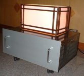

The De-lite lives. Nothing blew up the first time I turned it on. Not a bad sign.
But the voltages don't check out. First off, I'm getting 17 VDC on the output, despite using a 1000uf, 63V cap. The current draw is 2A, supply voltage 100V, approx 70V drop across bulb, and only 17 V on the drain of the FET. I'm using the IXTH20N50 part. Both the 1 ohm resistors are getting crazy hot, the heatsink is warm. The circuit is the one in Fig 5 on the article.
I'll be troubleshooting tomorrow. Any ideas?
Attachments
The De-lite lives. Nothing blew up the first time I turned it on. Not a bad sign.
But the voltages don't check out. First off, I'm getting 17 VDC on the output, despite using a 1000uf, 63V cap. The current draw is 2A, supply voltage 100V, approx 70V drop across bulb, and only 17 V on the drain of the FET. I'm using the IXTH20N50 part. Both the 1 ohm resistors are getting crazy hot, the heatsink is warm. The circuit is the one in Fig 5 on the article.
I'll be troubleshooting tomorrow. Any ideas?
Use 30w 1 ohm 1% resistor and heat sink them .
What you measure is capacitor charge. Put 1k resistor from output (the other end of that cap, where speaker should be connected) and you should have 0V - if not, it means that your 1000uF cap is leaky or faulty.... I'm getting 17 VDC on the output, despite using a 1000uf, 63V cap....
yup
from output side of cap - to gnd
Exactly - it slipped from the sentence somehow 😉
Thanks! 😛
Yes I tried them as current sources ,it seemed to work very good . The gain of the amp was slightly increased . And by listening the distorsion figure was better .
By the way I tried them not with power Jfets , but with the ixys depletion .
Thanks for the response.
I had been thinking about this for a while, but wasn't sure why no one had mentioned it earlier.
I suppose the next thing to try would be an aleph current source. It won't be a DeLite amp anymore, but it's fun to experiment,so why not.
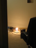
Thanks Juma and ZM. Yup, its working now. My first amp! Yay!! Its got the characteristic Class A midrange warmth. Although, I do hear a little distortion, especially on crescendos.
I have to say though, there is something about the whole "bulb" idea that is very beautiful. To look at that thing producing music and light at the same time is quite awesome. I had got a chipamp running for a few minutes some months ago, it sounded good, but it didn't make me happy like this one does. I feel like I understand this one much better and could probably fix it if something went wrong.
Has there been any alternate power supply improvement suggestions? Also, a CCS like the one in zen or the aleph CCS would raise the efficiency. Things to try in the coming days 🙂
Well, I just couldn't let it be. Tried the constant current source from ZV9. Referring to fig.2 in ZV9, I copied the top half of the circuit ie. everything above Q2. I read about P1 being adjusted to get half the supply voltage at the drain of Q2. I chose to ignore that. What happened as a consequence, is the cooking of the source resistor in the Delite.
Can anyone guide me as to how one would set the voltage at the drain of the IXTH part using this CCS? I'm guessing about 20V at the drain is good enough. What supply voltage though?
Can anyone guide me as to how one would set the voltage at the drain of the IXTH part using this CCS? I'm guessing about 20V at the drain is good enough. What supply voltage though?
... Can anyone guide me as to how one would set the voltage at the drain of the IXTH part using this CCS? ...
You obviously made a mistake in implementation of CCS (make a thorough check of all parts and connections). Also, you should post the complete and accurate schematic of your circuit.
Generally, CCS sets the current through the circuit, and IXTH's Source resistor is left with degeneration function only. Voltage on IXTH's drain depends on ratio of internal resistances inside the CCS and JFET.
Most simple way to adjust the voltage on IXTH's drain is to make your CCSs' current adjustable.
It is interesting to remember that the IXTH depletion mosfet , just as the Jfet in ZV9 is a self biasing part .Can anyone guide me as to how one would set the voltage at the drain of the IXTH part using this CCS? I'm guessing about 20V at the drain is good enough. What supply voltage though?
The "degeneration" resistor then sets the current of the circuit but also influences the gain of the amplifier . So does the load resistor ( in this case the light bulb ) .
If you build the amplifier with a CCS made of a self biasing Mosfet you'll find that to have around 17 volt at the drain of the IXTH ( gain device )you'll go for a power supply of about double of that value .
Implementing the Aleph CS probably will need a feedback resistor to control the voltages . Of course , the 1 ohm resistor cooked because of too much current around it since the Aleph CS was lacking P1 and (R14)and then the circuit itself wasn't able to set the Voltage of the gain D Mosfet .
You are the expert here Juma, but I kinda disagree with you. I think (hope) that I have not made a mistake in wiring up the CCS. The CCS should provide a fixed amount of current regardless of the conditions on the drain of the gain FET... well, at least an ideal one should. And of course within the range of the power supply.
My supply is about 40V and I was getting a steady 20V on the drain of the gain FET before the resistors began cooking. I didn't measure the current draw, but it didn't blow the 6A fuse. So, it was certainly less than that. I'm with Stefano here in that the problem lies with the IXTH part which is self biasing, as opposed to the JFET used in ZV9 or the MOSFET used in the original Zen.
One more note: The CCS isn't the the aleph CCS, its the one before that, shown in Fig.2 of ZV9. I'll post a schematic tonight so that its clear. And I will also check my connections once again.
Thanks guys!
- Home
- Amplifiers
- Pass Labs
- Pass "DeLite" Amp from BAF