Coolet,
what do you suggest as inrush-current delimiter?
Big resistor, thermistor?
Best regards - Rudi_Ratlos
what do you suggest as inrush-current delimiter?
Big resistor, thermistor?
Best regards - Rudi_Ratlos
for 220Vac, I would suggest 50r or two CL60 in series.
As the VA goes up and/or the smoothing capacitance goes up, one needs to increase the power rating of the limiter components.
I use 10r 5off in series for 300VA (T1A) to 600VA (T2A or T2.5A). This reduces the peak current at start up to below 7Apk and allows close rated mains fusing on 240Vac.
As the VA goes up and/or the smoothing capacitance goes up, one needs to increase the power rating of the limiter components.
I use 10r 5off in series for 300VA (T1A) to 600VA (T2A or T2.5A). This reduces the peak current at start up to below 7Apk and allows close rated mains fusing on 240Vac.
Your schematic looks good lineup.
This is exactly why my first schematic in my first post had 2 555s, to invert the signal.
Initially sounds more complicated than your version until you realise you can get two 555s in the one chip, ie the 556. I changed it to one on advice from others here.
I think both versions would work well (555 with inverting resistor or dual 555).
Yes.
My circuit with transistor, makes the same as LM556 .. your first circut.
So, maybe your first circuit is better .. needs no transistor. Just take OUTput from LM556.
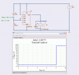
I tested one idea.
How to make the inverted operation, with one LM555.
Works! 🙂
The RC, resistor and cap.
When we have Resistor on top and Cap at ground
then the voltage across Cap will increase, until trigger 555.
Now, if we put Cap on top and Resistor at ground
then the voltage across Resistor/TR will decrease.
So, in first case voltage at TR will go from low to high.
In second case (see my diagram) voltage at TR will go from high to low.
The circuit will now power up relay from OUT Pin, after 8 seconds.
Attachments
Coolet,
what do you suggest as inrush-current delimiter?
Big resistor, thermistor?
Best regards - Rudi_Ratlos
for diy resistor are much chipper and it works.
I tested one idea.
How to make the inverted operation, with one LM555.
Works! 🙂
The RC, resistor and cap.
When we have Resistor on top and Cap at ground
then the voltage across Cap will increase, until trigger 555.
Now, if we put Cap on top and Resistor at ground
then the voltage across Resistor/TR will decrease.
So, in first case voltage at TR will go from low to high.
In second case (see my diagram) voltage at TR will go from high to low.
The circuit will now power up relay from OUT Pin, after 8 seconds.
You're a genius. Perfect. Using a single 555 is a cheaper and easier option. Well done for thinking outside the square. I have not seen a schematic for a 555 used in this way. We've made some good progress here. Thanks for your help!
Now, how should we power the circuit with minimal components? A zener regulator?
Last edited:
I power 12V relay directly from output of 12.6V filament voltage stabilizer. What can be more gentle than to short current limiting resistor in series with primary after all rectified and stabilized voltages are already up and running, and all transients and inrush currents already in the past?
Honestly, I don't understand the meaning of additional delay time, except some creative design exercise...
Honestly, I don't understand the meaning of additional delay time, except some creative design exercise...
I power 12V relay directly from output of 12.6V filament voltage stabilizer. What can be more gentle than to short current limiting resistor in series with primary after all rectified and stabilized voltages are already up and running, and all transients and inrush currents already in the past?
Honestly, I don't understand the meaning of additional delay time, except some creative design exercise...
I think I may need more delay than your method would provide as I have 600VA of transformer and ~300 000uF of capacitance to charge. I don't know though.
In any case it has been an interesting exercise and I like the idea of bringing it up slowly to be gentle to the components.
I think I may need more delay than your method would provide as I have 600VA of transformer and ~300 000uF of capacitance to charge. I don't know though.
But relay definitely knows as soon as they are already charged. 😉
I use 10A relay and 18 Ohm wirewound resistor (for 120V in USA).
Now, how should we power the circuit with minimal components? A zener regulator?[/QUOTE]
Many of us have 12V triggers from our preamps/receivers etc. Why not use that?
Many of us have 12V triggers from our preamps/receivers etc. Why not use that?
Many of us have 12V triggers from our preamps/receivers etc. Why not use that?
To power relay?
Exactly!
Suppose, you have more than one rectifier/filter in secondary. In primary you have a single common resistor that limits inrush current and causes soft start of all rectifiers all together. Thanks to this resistor and transformer all output voltages raise up proportionally to each other, and you can use one of them that better matches your existing relay as an indicator that all voltages are up and soft start process had been already done. You can short out now inrush limiting resistor: you don't need it anymore. Additional delay time is not necessary. Additional electronics being added contributes nothing more than probability of failure: the more of components in dependable chain you have, the less reliable result you get.
Lineup,
Just curious, what simulation software are you using?
Wavebourn,
Thanks for the input but I think I'm still going to persist with the 555 idea. I like the idea of a solid relay activation mechanism. I have concerns that your method may not switch the relay on hard enough, or may cause relay chatter. I'm probably being paranoid, but I think I can make the 555 concept work well.
Thanks,
Greg.
Last edited:
Electronic Workbench Multisim 10.0 Portable.rar
That it is portable means you can install it anywhere, on a USB-Stick for example.
The components library that is included is quite good,
but some audio transistors you have to add yourself.
One main alternative is LTSpice .... Here: Linear Technology - Design Simulation and Device Models
There are maybe more diy-members using LTSpice than EW MultiSim
The good thing when you use same simulator as others
is that you can let them run the same files as you have used.
Just send them a ZIP.
Lineup,
Thanks for that. I downloaded LT spice and am very impressed with it. I have simulated the soft start circuit and it works exactly as you described.
Cheers,
Greg.
Thanks for that. I downloaded LT spice and am very impressed with it. I have simulated the soft start circuit and it works exactly as you described.
Cheers,
Greg.
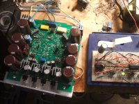
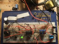
It works!
Having just lashed it together on a breadboard I can now confirm that the single 555 circuit posted by Lineup in post #24 of this thread works perfectly, and the 8s delay predicted by the simulation is pretty accurate. The circuit seems stable and repeatable and I will definitely be using it in my next project.
Cheers,
Greg.
To power relay?
Exactly!
Suppose, you have more than one rectifier/filter in secondary. In primary you have a single common resistor that limits inrush current and causes soft start of all rectifiers all together. Thanks to this resistor and transformer all output voltages raise up proportionally to each other, and you can use one of them that better matches your existing relay as an indicator that all voltages are up and soft start process had been already done. You can short out now inrush limiting resistor: you don't need it anymore. Additional delay time is not necessary. Additional electronics being added contributes nothing more than probability of failure: the more of components in dependable chain you have, the less reliable result you get.
Resistor on primary plus relay to short it that is powered by a secondary voltage and nothing else. I really like this and it makes sense.
I am looking at variable delay for warming mercury vapor rectifiers too though. Do you use protection circuitry for erroneous plate vs cathode voltage, or just plate fuse? (hmm hope this does not derail the thread)
-MW
Funny seeing this thread pop up now, I was just working on a way to soft start the large toroid transformer I should be receiving in a few days and had an idea come up with a circuit that I think ought to work. MHO, relays suck.... I try to avoid using them whenever possible. SS good
  😎
😎
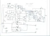
Line comes in through a fuse (of course😀) and through a small push on/push off switch to power a small 0.5VA transformer, such as this one, cost is about $4.
It's secondary is used to make an isolated +5.5V source that the main power switch controls. Since a 0.5VA transformer will not run up your power bill if left on continuously, like the big toroid and amp bias would, the Standby/On momentary switch can be used as power On/Off duty. I see a lot of equipment with this set up. Unlike most typicaly sized main power switches, the small push on/push off SW would probably have it's leads vaporized if trying to simply switch a large toroid directly onto the line.
The circuit starts up with the main transformer not connected to the line, and the LED is orange meaning the circuit is in standby mode. (I used a common cathode bi-color orange/green LED for parts simplicity.)
When the momentary switch is pressed, the monostable 555 circuit acts as a one shot with the time on set by Rt and Ct. This is the time in which
the main toroid primary is connected to the line in series with the current limiting power resistor. (SN7476 is a neg edge triggered JK FF.) Clock input level on the FF controlling photo-triac A is triggered from high to low so it changes state triggering triac A. After the time set by Rt and Ct is up, the 555 output goes from high to low triggering the FF for photo-triac B. Triac B bypasses triac A and the current limiting resistor placing the toroid primary onto the line. The reset of the 555 and CLE of FF A can be triggered by a logic 'fault' signal from the amplifier circuit via a photo coupler or just a regular transistor reseting the condition of standby, such as measuring if a fuse has blown or DC appears at the outputs.
You will loose a couple of mains volts to the triac, so triac B might need a small heat sink, and there will be a small switching 'notch' of a few volts on the mains line waveform from the firing of the triac but I did not notice any difference to the amp with the 3 EI transfos strung together that I'm using now. Since the triac is triggered full wave open, it's harmonic noise doesn't seem to be so bad.
So it seems to work peachy, now all I have to do is hurry up and wait for my transformer to arrive to see how it works.🙄
The question now is what would be the proper value for the current limiting resistor and timing interval for a 1400VA toroid?😕
I try to avoid using them whenever possible. SS good 😎Line comes in through a fuse (of course😀) and through a small push on/push off switch to power a small 0.5VA transformer, such as this one, cost is about $4.
It's secondary is used to make an isolated +5.5V source that the main power switch controls. Since a 0.5VA transformer will not run up your power bill if left on continuously, like the big toroid and amp bias would, the Standby/On momentary switch can be used as power On/Off duty. I see a lot of equipment with this set up. Unlike most typicaly sized main power switches, the small push on/push off SW would probably have it's leads vaporized if trying to simply switch a large toroid directly onto the line.
The circuit starts up with the main transformer not connected to the line, and the LED is orange meaning the circuit is in standby mode. (I used a common cathode bi-color orange/green LED for parts simplicity.)
When the momentary switch is pressed, the monostable 555 circuit acts as a one shot with the time on set by Rt and Ct. This is the time in which
the main toroid primary is connected to the line in series with the current limiting power resistor. (SN7476 is a neg edge triggered JK FF.) Clock input level on the FF controlling photo-triac A is triggered from high to low so it changes state triggering triac A. After the time set by Rt and Ct is up, the 555 output goes from high to low triggering the FF for photo-triac B. Triac B bypasses triac A and the current limiting resistor placing the toroid primary onto the line. The reset of the 555 and CLE of FF A can be triggered by a logic 'fault' signal from the amplifier circuit via a photo coupler or just a regular transistor reseting the condition of standby, such as measuring if a fuse has blown or DC appears at the outputs.
You will loose a couple of mains volts to the triac, so triac B might need a small heat sink, and there will be a small switching 'notch' of a few volts on the mains line waveform from the firing of the triac but I did not notice any difference to the amp with the 3 EI transfos strung together that I'm using now.
Since the triac is triggered full wave open, it's harmonic noise doesn't seem to be so bad. So it seems to work peachy, now all I have to do is hurry up and wait for my transformer to arrive to see how it works.🙄
The question now is what would be the proper value for the current limiting resistor and timing interval for a 1400VA toroid?😕
Attachments
Last edited:
Hi,
I didn't know that photo triacs existed. Is Solid State switching more or equal or less reliable than relay?
The control method seems quite nice.
I'll need to re-read this a few times to fully understand what you have built.
Thanks.
I didn't know that photo triacs existed. Is Solid State switching more or equal or less reliable than relay?
The control method seems quite nice.
I'll need to re-read this a few times to fully understand what you have built.
Thanks.
Hi
Photo-triacs have been around for a while now. The beauty of using a photo-triac to trigger a triac or SCR other than isolation is it triggers automatically in both directions with a logic signal driving the LED since the triac must be triggered every half cycle to be on as a switch. Makes it easy.🙂
Photo-triacs have been around for a while now. The beauty of using a photo-triac to trigger a triac or SCR other than isolation is it triggers automatically in both directions with a logic signal driving the LED since the triac must be triggered every half cycle to be on as a switch. Makes it easy.🙂
- Status
- Not open for further replies.
- Home
- Amplifiers
- Solid State
- I think I have a neat, simple and easily implemented idea for a soft start circuit