Lucas, how can you get proper DC with only 2 powerdiodes (TO 220) ?
Salas showed me how. It's covered earlier in this thread. It's quite possible for a single rail using a twin secondaries centre tapped transformer. I had to remove the traces and do it point to point in order to use them in those positions with the half board, but I could have cut no traces at all if I'd kept the board whole, and used 2x alternate diodes. Search back and check it out. It works just as well as a bridge.
Last edited:
googlegooglegoogle, aha 2 half wave rectifiers making on full wave one. Making the same DC output as a bridge rectifier. well, well.
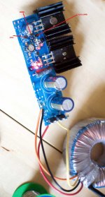
Have checked against PCB ''Xray'' and simulator. You have put Vref LEDs & resistor OK. The only one that looks flat and I don't know if its oriented as it should is the BC550 gain error amp element. What is the flat transistor, I have noted as ''gain''? BC550s are TO-92, is there a different case? Else its put reversed and partially obscured in the photo's angle.
The ''CCS'' 2SK170 if working right sets a constant current through the voltage reference. The BC550 amplifies against output disturbances being referenced by the LEDs & resistor. And its loaded by the ''Col. Load'' 2SK170 that is a CCS load to help BC550 go fully strong doing its business. If any one of those 3 elements had it bad during the smoky 10R no lights test, must be the culprit. The 2 dim LEDs in the voltage reference imply low current. You did well that you replaced two of those 3legged bugs, I hope its not the 3rd one. Also there must be a 470R resistor behind the output capacitor that I can't clearly see, parallel to the output Mosfet.
The ''CCS'' 2SK170 if working right sets a constant current through the voltage reference. The BC550 amplifies against output disturbances being referenced by the LEDs & resistor. And its loaded by the ''Col. Load'' 2SK170 that is a CCS load to help BC550 go fully strong doing its business. If any one of those 3 elements had it bad during the smoky 10R no lights test, must be the culprit. The 2 dim LEDs in the voltage reference imply low current. You did well that you replaced two of those 3legged bugs, I hope its not the 3rd one. Also there must be a 470R resistor behind the output capacitor that I can't clearly see, parallel to the output Mosfet.
Attachments
The flat GAIN transistor is "ZTX 550 ND" It is from my F5 BOM. Probably the wrong part I now see. Ahhhhh...that'll do it!
With the 2SK170s and IRFP9240s being so ubiquitous, I figured the 550s would be too. Not so. My bad.
I'll have to wait for the real 550C part to arrive then, at very least.
Thanks so very much. You're awesome! 🙂
🙂
With the 2SK170s and IRFP9240s being so ubiquitous, I figured the 550s would be too. Not so. My bad.
I'll have to wait for the real 550C part to arrive then, at very least.
Thanks so very much. You're awesome!
🙂Here is the data sheet of the LED's you are using. maybe someone can see if it's the LED's
They don't utilise the flat side as an indicator as I see in their mech. drawing. Very rare and a trap indeed. Short & long legs designated as normal.
The flat GAIN transistor is "ZTX 550 ND" It is from my F5 BOM. Probably the wrong part I now see. Ahhhhh...that'll do it!
With the 2SK170s and IRFP9240s being so ubiquitous, I figured the 550s would be too. Not so. My bad.
I'll have to wait for the real 550C part to arrive then, at very least.
Thanks so very much. You're awesome!
Boing!🙂 That's a PNP. BC550 is an NPN.
Hi Salas, (or Andrew if you're around 🙂 )
Now, I did what you said, and arrived at 4K (I believe you said 3.978K was the right value) for my shunt reg to arrive at 30v DC.
I did so with a combination of series and paralleled resistors: 3k3 + (3x1K8=600R) + 100R = 4K0 on the dot.
My reg outputs 30v DC, but I had thought, perhaps wrongly, that a shunt reg is supposed to be rock steady in DC output, and this isn't. It fluctuates between 29.925v & 30.50, sometimes at the rate of about 1/100th of a volt per second in a steady climb or fall. Is that to be expected, or does it indicate a fault? I left it on, unloaded for about 10 minutes, by which time it was pretty hot in the sinks, but still it was fluctuating a bit (perhaps less though).
Is this settling in stuff?
I also noticed that when measuring Vdrop on the leds, they fluctuated for about 30 seconds before settling on a voltage (about 1.7Vf on mine).
Many thanks
Last edited:
Normal. The Jfet drifts thermally a bit. When having a resistor ref it directly translates. The higher Vo the more R, the easier. If made with leds only, they are stiff to minute current changes, after initial settling. After enough time, if in a box, it settles to some ambient temp & Vo. Does it change if you blow over the ''ccs'' jfet? If yes, that's it. Does not have to do with regulation, just reference Vout. In such a small bracket you describe, inconsequential for the bias of your audio circuit. It would be no good if it drooped under signal peaks. Its the voltage ref that gives the drift characteristic not if its a shunt or series for current. This ref proved simple to make subjectively good. If you use even bigger than 100uF cap across the ref it normally gets even steadier towards DC, but it may come across heavier in the listening.
OK. That makes a lot of sense. I actually understand this time 🙂
Hypothetically then, is it possible to use more leds to create a more locked reference for 30v instead of the resistor? Not easy on this board, I understand, but theoretically.
Not that I necessarily will do that. I'm just asking...
Oh, and I've finished it then...Wooohooo! Thanks so much Salas.
Hypothetically then, is it possible to use more leds to create a more locked reference for 30v instead of the resistor? Not easy on this board, I understand, but theoretically.
Not that I necessarily will do that. I'm just asking...
Oh, and I've finished it then...Wooohooo! Thanks so much Salas.
Last edited:
Too many leds for 30V... Maybe no drift but building up noise. This passive ref you got has nice attributes. Just use very short cables to your Atlantic and have a listen. If its all well and If it betters your previous, that's the essence. Let us know.
I'm sure the voltage drift will be inaudible, as you say, as it relates to ambient temperature, which should stabilise, not regulation as such.
What about LEDs with higher Vf? Just a thought...
How do I measure the current of the reg? Surely that must be pretty rock solid for SQ?
This thing gets pretty hot when unloaded....
What about LEDs with higher Vf? Just a thought...
How do I measure the current of the reg? Surely that must be pretty rock solid for SQ?
This thing gets pretty hot when unloaded....
Hi,
the cooler you keep all the semiconductor junctions, the lower the temperature drift.
The output voltage is Vref+Vbe. Both of these are affected by temperature.
Changing the current or the temperature will change the output voltage.
the cooler you keep all the semiconductor junctions, the lower the temperature drift.
The output voltage is Vref+Vbe. Both of these are affected by temperature.
Changing the current or the temperature will change the output voltage.
How do I measure the current of the reg? Surely that must be pretty rock solid for SQ?
This thing gets pretty hot when unloaded....
The main CCS current can be translated on the 10R 5W Vdrop. The output current has to change dictated by the load needs.
The output current has to change dictated by the load needs.
Oh, OK. So the rest of the current, the unused bit, is shunted to the sinks, right?
Sorry to bombard you with questions Salas, but I am ordering an R-core 15-0-15 from eBay China for the DCB1, as they seem to be the dog's bollocks from what people say, and I thought I might get one for my phono stage too. For 30v DC, would 35-0-35 at 50-80VA be my best option, or what?
I have a box that will struggle to fit my phono stage in and keep the big 25-0-25, 120VA toroidal away from the signal, and R-core will help with that I think.
I have a box that will struggle to fit my phono stage in and keep the big 25-0-25, 120VA toroidal away from the signal, and R-core will help with that I think.
Sorry to bombard you with questions Salas, but I am ordering an R-core 15-0-15 from eBay China for the DCB1, as they seem to be the dog's bollocks from what people say, and I thought I might get one for my phono stage too. For 30v DC, would 35-0-35 at 50-80VA be my best option, or what?
I have a box that will struggle to fit my phono stage in and keep the big 25-0-25, 120VA toroidal away from the signal, and R-core will help with that I think.
Could you post the link to those R-Core Transformers please?
Could you post the link to those R-Core Transformers please?
Just search "R-core" in eBay - they're all from China or Hong Kong, so make sure you're looking at worldwide listings. If you can't find any doing that, look on eBay.co.uk, and you'll see them.
Oh here, I've got the link now: R-core
Scroll down the listing for other voltages. Careful though - they're not massive transformers and not highly ampage rated! Also, the listing is not the clearest as none of them have a VAC rating.
Last edited:
- Status
- Not open for further replies.
- Home
- Amplifiers
- Power Supplies
- Using the HYPNOTIZE as a general shunt reg PCB