Hi Andy, it would be interesting to try one of Rod's supplies after an LC stage for the filaments. I was thinking about doing somehting like that for my next preamp project....
Yes, absolutely. I know from experience how good Rod's supplies are - as you do! The LC stage for the filaments is a good idea. I have a pair of 280mH chokes for you if you wish. I feel like putting LC supplies right through my amp as well. The chokes annihilate LM1084 regs - and to think how long I was happily using those.
Heatsinking may be an issue with Rod's filament board, though as a final stage before the filaments for 10Y in filament bias it just needs to pass 1.25A and drop 4 volts or whatever it's happy with. What I didn't quite get was the surge at turn on with LC which shut down LM1085 regs - they're rated for 2.5A!! The LM1084 coped, and they're rated 5A. Don't know how this would affect Rod's board.
Andy
hi Andy
Nominal headroom for the boards is 5V, but that's to allow a raw dc which varies + or - 1V.
If you have a stable supply, 4V is enough. The first samples of the boards work fine even with 3.5V - but in most cases the higher voltage is better. THis is one improvement in the new design - full performance even with low voltage headroom.
With 1.25A in the 10Y, the transistors are dissipating only about 2.7 ... 3.3W each for 5...6V headroom. If you have some ventilation, a 5K/W heatsink like the little AAVID KM75 will suffice - it's only 75mm (3 inch) wide, and easily clips the transistors in place.
KM75 is in the picture, tested for 24 hours at 6V headroom in a 300B configuration, where the heatsink reached about 85 deg C in a 25 deg C environment.
Attachments
Yes, absolutely. I know from experience how good Rod's supplies are - as you do! The LC stage for the filaments is a good idea. I have a pair of 280mH chokes for you if you wish. I feel like putting LC supplies right through my amp as well. The chokes annihilate LM1084 regs - and to think how long I was happily using those.
Heatsinking may be an issue with Rod's filament board, though as a final stage before the filaments for 10Y in filament bias it just needs to pass 1.25A and drop 4 volts or whatever it's happy with. What I didn't quite get was the surge at turn on with LC which shut down LM1085 regs - they're rated for 2.5A!! The LM1084 coped, and they're rated 5A. Don't know how this would affect Rod's board.
Andy
Andy, Sounds like the LM108x is unstable to me. It's quite possible it doesn't like the inductive large loop area of the filament as a load.
My design has been tested with large air-cored inductors as a LOAD
as well as with long supply cables and spaghetti-wired filament leads.
In all cases, the scope test, portable radio monitoring, and LTspice simulations show full stability, including during switch-ON and OFF transients.
THe testing programme is one reason the design took a while to appear.
The fact that only ONE component terminal connects to each filament terminal is a great help - just two outputs. There are no feedback loops connected to the filament at all. This sounds better than all other architectures, and is stable under any realistic load.
Schematic will be available, as soon as I've finished all the build definitions & intstructions. Architecturally it's identical to the previous edition, but with a buffer for the CCS supply, adjustable current trimming, and wonderful low-voltage transistors.
Just trying the difference in choke input between the Hammond 159ZC at 60mH and the other chokes I have at 280mH. It's the same generic sound. Sound is just a little less full and rounded. So bigger is better, though the sound is similar. Haven't tried switching them in the second choke position where Rod thinks it will make a difference.
It also occurred to me that with filament bias, the changes in filament supplies may well be more audible than when feeding filaments in the conventional way.
andy
It also occurred to me that with filament bias, the changes in filament supplies may well be more audible than when feeding filaments in the conventional way.
andy
It also occurred to me that with filament bias, the changes in filament supplies may well be more audible than when feeding filaments in the conventional way.
andy
That is completely true.
A low ac impedance affects anode current (badly), whereas any power supply noise at the cathode resistor is the same as injecting noise into the grid.
Both these effects are nasty.
Just trying the difference in choke input between the Hammond 159ZC at 60mH and the other chokes I have at 280mH. It's the same generic sound. Sound is just a little less full and rounded. So bigger is better, though the sound is similar. Haven't tried switching them in the second choke position where Rod thinks it will make a difference.
It also occurred to me that with filament bias, the changes in filament supplies may well be more audible than when feeding filaments in the conventional way.
andy
Did you change both chokes or just the first one?
Schematic will be available, as soon as I've finished all the build definitions & intstructions. Architecturally it's identical to the previous edition, but with a buffer for the CCS supply, adjustable current trimming, and wonderful low-voltage transistors.
Great stuff thanks Rod. I'm eagerly awaiting this. 🙂
Andy will be nice see a pic.... no problem for diy mess😛
Rob filament bias will be good , hope Andy will have time to test grid vs filament bias
Rob filament bias will be good , hope Andy will have time to test grid vs filament bias
Member
Joined 2006
Good thinking Rod 😉
That's so convenient! Thanks so much. And it's nice of you to publish the circuit too.
Will report once your regs are installed. Yeah, could try out 26/01A/112-A here soon 😀
That's so convenient! Thanks so much. And it's nice of you to publish the circuit too.
Will report once your regs are installed. Yeah, could try out 26/01A/112-A here soon 😀
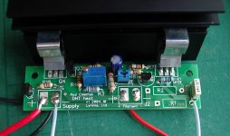
Here's a photo of the 26 (1.5V 1.05A) and 01A(5V 250mA) switchable filament driver. Just supply a raw dc of about 10V, and the board will heat 250mA filaments. Insert the PC-Motherboard Jumper link (in the centre), and the rated current rises to 1.05A for a 26. The extra large resistor soaks up the difference in voltages, instead of the transistor/heatsink - so these run cool in either mode.
In both modes, the 25-turn trimmer can accurately adjust filament current.
Special design for Cheung, these will be ready soon.
Hi Rod,
do you sell theses 26 boards?
KR Hauke
Hi Rod,
do you sell theses 26 boards?
KR Hauke
hi Hauke,
Yes, I will have them to sell.
I must prepare drawings and instructions first. Also, Power supply design recommendations, and heatsink compatibility. Then - they will be available!
hi Hauke,
Yes, I will have them to sell.
I must prepare drawings and instructions first. Also, Power supply design recommendations, and heatsink compatibility. Then - they will be available!
Rod, Will you provide it as a kit? If so I am interested as well. It is difficult to find most of the components for your filement PSU here in my place.
Rod, Will you provide it as a kit? If so I am interested as well. It is difficult to find most of the components for your filement PSU here in my place.
Hi, Yes, Full kit will be available - just add a raw dc supply (trafo, rectifier, caps).
I prefer NOT to sell PCB-only. With a full kit, all the regulators should work just like the ones I have built, measured, and qualified. I'll PM some more info.
Hi, Yes, Full kit will be available - just add a raw dc supply (trafo, rectifier, caps).
I prefer NOT to sell PCB-only. With a full kit, all the regulators should work just like the ones I have built, measured, and qualified. I'll PM some more info.
Thanks Rod. great help.
Hi, Yes, Full kit will be available - just add a raw dc supply (trafo, rectifier, caps).
I prefer NOT to sell PCB-only. With a full kit, all the regulators should work just like the ones I have built, measured, and qualified. I'll PM some more info.
Hi Rod,
I,m interested in this filament reg kit when will be available.
Regards,
Anto
- Home
- Amplifiers
- Tubes / Valves
- #26 pre amp