I'm excited about this new I/V and will be using the "swap from IVY order" button as soon as I see it.
Frank in Mpls.

I could not find a good way to make this work with the backend system, so if anyone wants to make such a swap, please email me.
Ht,
Isn't it a good idea to post the manual?
The manual will be up on the site as soon as I finish it. 🙂
There is not much more to it then what I have already posted here. So it won't take me too long. Don't worry.
Just ordered, and looking forward to hearing my Legato. Been thinking about trying Sowter transformer off the the DAC, but I remember Russ mentioning that 9018 likes load <1 Ohm, not appropriate for tranny. But it's a cool idea put tranny after the IV stage.
Thanks Russ and Brian for bringing Legato to us diy'ers, and congrats on the new product.
Rich
Thanks Russ and Brian for bringing Legato to us diy'ers, and congrats on the new product.
Rich
Seems like quite a few people are interested in trying a transformer after the legato.
Russ, you mentioned, that you would leave the LPF. Could you please explain further why its better to have the on board filters and what is special about lower order in this context. I initially got the idea of removing the on board filter because the legato website said "optional filtering".
Russ, you mentioned, that you would leave the LPF. Could you please explain further why its better to have the on board filters and what is special about lower order in this context. I initially got the idea of removing the on board filter because the legato website said "optional filtering".
Sure, just about any standard pinout dual opamp should be ok as long as it is unity gain stable.
Film Caps for output?s
I was planning on using some larger film caps for output coupling, and I wanted to run them from the board straight to the output jacks (XLR only) to keep the lead lengths short. On the schematic I now see that R29-32 follow the caps, excuse my ignorance, but can I have the caps after these resistors: jumper C5-7, then input lead from film caps to +/- outputs, then output from caps directly to XLR jacks? Or do I have to run leads from the caps to and from the board at C5-7?
I was planning on using some larger film caps for output coupling, and I wanted to run them from the board straight to the output jacks (XLR only) to keep the lead lengths short. On the schematic I now see that R29-32 follow the caps, excuse my ignorance, but can I have the caps after these resistors: jumper C5-7, then input lead from film caps to +/- outputs, then output from caps directly to XLR jacks? Or do I have to run leads from the caps to and from the board at C5-7?
It depends on if you want to use the BAL/SE converter. The input to the BAL/SE should be AC coupled. So you can do a couple things.
1) Keep the on-board caps just for the BAL/SE and add another set of caps for balanced output.
2) Take the signal at the input side pads of the caps and run the signal back to output side pads the just as if it were an on-board cap.
All you really need to know is that the BAL/SE stage needs to be AC coupled to prevent offset. You can try it DC coupled, but its likely to have a good amount of offset.
Cheers!
Russ
legato as line amp
Hi i ordered 1 legato yesterday. I will use it as 1/v converter after my ez dac,output from pcm 1794a, i will use it as replacement for ad 8610.
Can i use it as line amp, and can i connect a potmeter on legato.
Hi Guys,
It is very difficult for me to comment on such questions. Because you are asking me for a subjective opinion. Still, I will do my best.
These two circuits are so extremely different.
They approach the challenge of accomplishing excellent linearity and high dynamic range in two very different ways.
IVY-III is "technically" superior and sounds incredible. It uses the same fully symmetrical feedback scheme as Nelson Pass' excellent super symmetrical applications. I am never disappointed in listening to it. It is DC coupled, and it - like most of my modules - really shines when used with fully balanced gear, but it is by no means lacking when used single ended. It combines active I/V with passive filtering in a way the leaves the audio signal both clean and crisp. The two stages of IVY-III work in concert to excellent effect.
The Legato and the IVY-III have this in common, an opamp based BAL/SE stage. Here is why, there simply is no better active solution I have found (yet). The wonderful thing is, there is no harm if you decide not to use it. You can use a transformer or other mechanism to get single ended output from the balanced signals. It is up to you. In the meantime you can use it as is and simply enjoy it.
The legato uses no opamps and no global feedback *at all* to achieve its excellent linearity. It instead uses a bit of local feedback which is called a CFP (complimentary feedback pair) which is a way to achieve extremely high trans-conductance and linearity from one logical transistor which is actually made up of one PNP and NPN pair. Much higher trans-conductance than could be achieved with any single FET or BJT is accomplished using the CFP. Legato as a system is quite simple. A classic common base amplifier with a CCS fed buffer. Very clean, very quiet, very musical, and impossible to forget.
So in the end. I can only recommend this: Try them both and decide which you like best for yourself. 😎 I have yet to be able to decide which I like best. I use both. The bottom line is you are not going to be disappointed with either of them. 🙂
Cheers!
Russ
Hi i ordered 1 legato yesterday. I will use it as 1/v converter after my ez dac,output from pcm 1794a, i will use it as replacement for ad 8610.
Can i use it as line amp, and can i connect a potmeter on legato.
One other note, even if you don 't use the optional class A buffer the output impedance at the balanced outputs is pretty low. Something like 150 Ohms. Many people will elect to go this route to drive power amplifiers as even a 10K load would work just fine, in fact the only effect of the load would be to very slightly attenuate the signal and of course change the corner of the high pass.
Russ, out of curiosity, what do you use for your 'reference' balanced power amp? A Sympatico or some other custom design?
Russ, do I recall correctly that Overture and Sympatico amplifier input impedance is on the order of 2200 Ohms? If you are using a stock Sympatico as your reference amp and report that the Legato's output buffer is preferable, then that's a nice hint. Comments?
[...got my Buffalo/Legato components waiting and they will be my 'reward' for finishing a dragged-out remodeling project of which I am very weary! 😉 BTW Russ, I decided to stick with my old PCI interface and will stop clamoring for the XMOS solution. 😱 I will instead replace my dying PC mobo with one that is a lot simpler and hopefully sounds better.]
The Sympatico input impedance is about 100K. 🙂
I am using it with the Legato. I do not use the Legato with output buffer for anything other than headphones right now.
I am using it with the Legato. I do not use the Legato with output buffer for anything other than headphones right now.
For those who haven't found it yet, the first cut of the manual is up on the Legato page.
I will be adding more content to it early next week (going away for the weekend) such as output wiring diagrams, and diagrams for not including the buffers.
As an additional note, we have changed the current adjustment pots in the Placid BP kits to allow for easier adjustments for higher current loads (200R to 20R). You can still use the 200R if you have an earlier kit; the 20R just eliminates a lot of dead space int eh adjustment. So, you may find you have two sets of VR1 and VR2. Use the 20R.
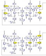
It doesn't make sense.
Manual says:
"Omitting the output buffer:
Omit: QN5-QN12, R25-R28"
According to the schematics, this will end up with something not so symmetrical.
Manual says:
"Omitting the output buffer:
Omit: QN5-QN12, R25-R28"
According to the schematics, this will end up with something not so symmetrical.
Attachments
Last edited:
It doesn't make sense.
Manual says:
"Omitting the output buffer:
Omit: QN5-QN12, R25-R28"
According to the schematics, this will end up with something not so symmetrical.
Yes you are correct. We will correct the manual.
It should be :
Omit QN7-QN14
Ok, thanks to Brian, the manual has been revised. Thanks for spotting that error. Also it should be noted that all of the omitted buffer parts have an "X" in them on the PCB. And the places where the jumper goes have a small line between the two pads. I just use a small piece of left over resistor lead.
Last edited:
Thanks...
Russ:
I am not using the BAL/SE converter (no need for SE outputs), so I'll just jump C5-8, and run the outboard caps from the output terminal to the XLR jacks-this seems like the most direct approach, avoiding long leads, etc.
It depends on if you want to use the BAL/SE converter. The input to the BAL/SE should be AC coupled. So you can do a couple things.
1) Keep the on-board caps just for the BAL/SE and add another set of caps for balanced output.
2) Take the signal at the input side pads of the caps and run the signal back to output side pads the just as if it were an on-board cap.
All you really need to know is that the BAL/SE stage needs to be AC coupled to prevent offset. You can try it DC coupled, but its likely to have a good amount of offset.
Cheers!
Russ
Russ:
I am not using the BAL/SE converter (no need for SE outputs), so I'll just jump C5-8, and run the outboard caps from the output terminal to the XLR jacks-this seems like the most direct approach, avoiding long leads, etc.
- Home
- More Vendors...
- Twisted Pear
- Legato or IVY III outputs for Buffalo II?