Hello baldin...
please see my earlier post/s ..... the detecting "part" taken from ucd700 pdf.... it works 😀 combined with the MOSFET N/P switches(link to scheme posted also).... it(supply) disconnects when inputed with iether a + or - ......
my problem?? is how to -isolate- ??? the UCD oscilation from the on/off mosfets..... maybe a CLC between mosfet switch AND UcD is enough.....
did it with opto-coupler/isolator(between DC detection && mosfet switches)... im off with just using level shifters/transistor switches/inverters(only works BEST in sim, not in real world)...
still in proto though.... need a way to -MIX- , or monitor 2 ucds with just a single mosfet switch/ AMP PS...
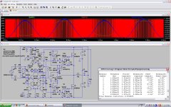
Since rx5's schemos are gone, heres a simulation based on hypex's unvalued schematic:
Im almost considering trying to build one.
An externally hosted image should be here but it was not working when we last tested it.
Im almost considering trying to build one.
You might want to take a look at this ...
Simulated with 1Khz input at 2V amplitude
+/- 74 Vdc
0.5% THD
450W RMS
650 Khz switching freq
Of course these are simulated results, but taking in consideration that LT spice is a reliable tool you could reach those results using a 2 layer pcb design.
Best Regards,
Savu Silviu
Simulated with 1Khz input at 2V amplitude
+/- 74 Vdc
0.5% THD
450W RMS
650 Khz switching freq
Of course these are simulated results, but taking in consideration that LT spice is a reliable tool you could reach those results using a 2 layer pcb design.
Best Regards,
Savu Silviu
Attachments
Very strange, asymmetrical frequency change.
blue trace is a momentary power 🙂 green trace in background is output voltage...
0.5% THD
450W RMS
...
Of course these are simulated results, but taking in consideration that LT spice is a reliable tool you could reach those results using a 2 layer pcb design.
Do not forget about stabilized PSU, needed to achive the same results in practice 😉
Simulated with 1Khz input at 2V amplitude
+/- 74 Vdc
0.5% THD
450W RMS
650 Khz switching freq
Of course these are simulated results, but taking in consideration that LT spice is a reliable tool you could reach those results using a 2 layer pcb design.
Best Regards,
Savu Silviu
hi savu did you manage to get your amp to work in real life with that voltage?
- Status
- Not open for further replies.
- Home
- Amplifiers
- Class D
- my 1st ever D-amp, WORKING!!!