In Atwoods paper it seems that some of the ringing is self damping anyway, so that's a good thing. But with music, it's just as likely to be started again shortly anyway.
It sounds like a good reason to put the OPT outside of any feedback loop, you wouldn't want that ringing going through the amp again. Maybe a small zobel could nab it on the secondary?
Wrt SS CCS 'harshness' - it appears to me that it's an artifact of the silicon devices' junction capacitances. Intrinsic silicon as used in semiconductor junctions has a K ~ 12 - higher than that of an electrolytic capacitor. Sprinkling these nonlinear capacitances through a purportedly tube circuit is not something I would do unless there was no other way to accomplish the desired overall function.
Last edited:
Wrt SS CCS 'harshness' - it appears to me that it's an artifact of the silicon devices' junction capacitances. Intrinsic silicon as used in semiconductor junctions has a K ~ 12 - higher than that of an electrolytic capacitor. Sprinkling these nonlinear capacitances through a purportedly tube circuit is not something I would do unless there was no other way to accomplish the desired overall function.
That is, however, not true of any competently designed CCS. What's the TOTAL capacitance of a DN2540 cascode, for example? How nonlinear is it?
I'm unaware of intrinsic silicon being used at the junctions in FETs or bipolars. Could you give me an example?
Hello, Sy -
'Intrinsic' silicon means crystalline silicon, which is what silicon semiconductor junctions are essentially composed of, along with doping compounds. The relatively tiny concentrations of junction doping compounds have little effect on the k of the intrinsic silicon. The insulator silicon dioxide is typically used for MOSFET gate junctions, and that has a lower dielectric constant, of about 4.
If you use a silicon junction device of any sort that is effectively in the audio path, you pretty much have to work around its junction capacitances as best you can to minimize their sonic contributions.
Last edited:
If you use a silicon junction device of any sort that is effectively in the audio path, you pretty much have to work around its junction capacitances as best you can to minimize their sonic contributions.
But is CCS effectively in the audio path?
there are suitable Si devices for tube ccs with single digit pF Crss - and properly done cascode can reduce audio frequency Coss effects below that level
the only limitation is that you really want to have ~20 V headroom for the Si ccs to keep the parasitic junction C away from the "ugly" nonlinear "triode"/saturation region - beyond that the C nonlinearity tends to a low sqrt(V) law
http://www.diyaudio.com/forums/tubes-valves/165101-cascoded-ring-two-plate-load-2.html#post2162798
shows a bjt ccs sim with GigaOhm |Z| @ 10 KHz -just how much room for audible Si capacitance nonlinearity is left when you parallel that with few KOhm plate R?
Last edited:
If you use a silicon junction device of any sort that is effectively in the audio path, you pretty much have to work around its junction capacitances as best you can to minimize their sonic contributions.
Sure. That's why it would be not smart to use power MOSFETs as current sources for tubes with anode currents below 1 miliamper.
There are no free lunch in electronics. Everything means optimization. No "Good" or "Bad" components exist in the Universe. You know, one Seminary student told me that even Bible doesn't contain dogmas!
If this hasn't already been covered, has anyone considered what some of these SS CCSs do above the audio band? Most impedance plots show their impedances collapsing before 20 kHz. Coupled with low Rp high Gm tubes anything's possible well within their nominal operating range. Take it as voodoo but I've always found, at least with simple CCSs like a solo IXYS, burning off as much static DC as practical with a series resistor used like a plate stopper just sounds better.
If this hasn't already been covered, has anyone considered what some of these SS CCSs do above the audio band? Most impedance plots show their impedances collapsing before 20 kHz.
Keep working stage impedances as low as possible, low rp etc to swamp out the hidden "silicon cap insigifigant" when compared to the internal Miller tube
C a-g. Generally, for audio work any extra external capacitance placed on the anode raises the distortion. This is guaranteed and often most misunderstood. A compromise is required for phase and HF stability. So it makes sense to use CCS for triode stages or even better, triode configed pentodes to reduce this hidden C problem.
A clue to this dummy animal: look at what happens when a Zobel is often fitted to the first anode stage in p-p amps. Je higher the snubbed cap value, the higher the thd, ( I wonder how many have noticed this ???) despite global nfb raising the effective anode impedance which in reality is compounding matters.
A M Jones mentions: Valve Amplifiers 3rd ed, p.449 the application of global nfb is a achilles heel. So we have a nice shiny tube for the first stage which is now being asked to "slow down" for the sake of the other stages of the amp. What a waste ! Choosing snubber values is a complicated issue which also effects the tonal midrange and upper register.
Ultimately,the final stage of the amp should be the one that determines the bandwidth. A little more complicated than one thought and to solve it requires skill. So I don't use a CCS for first stage anode loads unless there's a very good reason for doing so.
richy
If this hasn't already been covered, has anyone considered what some of these SS CCSs do above the audio band? Most impedance plots show their impedances collapsing before 20 kHz. Coupled with low Rp high Gm tubes anything's possible well within their nominal operating range. Take it as voodoo but I've always found, at least with simple CCSs like a solo IXYS, burning off as much static DC as practical with a series resistor used like a plate stopper just sounds better.
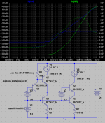
Do you remember my Tower-III hybrid thread?
Here is 6P15P driver from that thread, in triode mode, loaded on Gyrator. 100 KHz, 120V P-P, 3K load.

One more picture from that thread: 2 stages, 6N1P triode and 6P15P in triode mode, both loaded on Gyrators. Feedback from output to cathode of 6N1P.
100V P-P, 50 KHz. Is it above an audio band?

100V P-P, 50 KHz. Is it above an audio band?
If this hasn't already been covered, has anyone considered what some of these SS CCSs do above the audio band?
Take a look at Walt Jung's measurements of the simple MOSFET cascode that I use. I think they were in AX in April or May, 2009. No problem-o with bandwidth.
I forgot the upward slope of Walt's curves are partially an artifact of his measurement jig. That said, what happens at 10 or 50 MHz where many of these tubes are still hot to trot is uncertain. Some complaints about harshness could be related to stability issues with offender tubes.
I forgot the upward slope of Walt's curves are partially an artifact of his measurement jig. That said, what happens at 10 or 50 MHz where many of these tubes are still hot to trot is uncertain. Some complaints about harshness could be related to stability issues with offender tubes.
Here is another picture from that thread, 1 MHz squares, 100V peak-to-peak, the same 2 stages both Gyrator loaded, is it symmetrical enough? Any stability issues?

Some complaints about harshness could be related to stability issues with offender tubes.
True of high transconductance tubes in general, irrespective of type of loading. Same with unexpected hum, noise, and microphonics- they're often a symptom of VHF oscillation.
The thing about Walt's graphs is understanding the scale (though make sure you see the follow-up letter rather than the original article). Whether you're 1000 or 10000 times higher than rp is irrelevant to stability, gain, or distortion. That's one reason I never used the fancy CCS that Gary Pimm designed- it's a tour de force of CCS design, but so past the point of where the performance ceases to matter that the complexity and parts count steered me to the simple cascode.
Wavebourn, I'm not talking about your implementation but simple single chip devices like the IXYS. Do we know what plate load, particularly reactance, these present at very high frequencies? The scale is clear SY but I don't see any reason to take on behaviour at 200K what a device does at VHF. I seem to recall some of your old posts arguing for 100 MHz scopes having value when checking for circuit oscillations. A series resisitor is a very cheap and effective way to set a know, resistive and unambiguous min. Without further device data, in my mind that combination of cost/safety factor is good engineering.
In case we're slipped into the silly dualism that can plague these discussions, I use SS CCSs all the time and am not arguing against them but just trying to sort a possible mechanism for complaints of harshness.
In case we're slipped into the silly dualism that can plague these discussions, I use SS CCSs all the time and am not arguing against them but just trying to sort a possible mechanism for complaints of harshness.
Notice the resistors in the plate circuits of the HMV and ImPasse?😀 It's all part of "competent design."
In case we're slipped into the silly dualism that can plague these discussions, I use SS CCSs all the time and am not arguing against them but just trying to sort a possible mechanism for complaints of harshness.
And we agreed with you that the reason of such behavior is often oscillation. Does not matter: oscillates it with CCS, or other load, it may sound harsh. Resistor is cheap, and it sucks an energy out of a resonant tank, so an anode stopper is a good idea. Also, if conditions allow some voltage drop, a resistor in series with a CCS is a good idea. You may see on the picture a resistor in series with Gyrator; it acts as a heatsink as well.

As far as high-order harmonics, instrumentation-type CCS's (with super-high OLG masking nonlinear inner workings) such as using an LM312 or general chips for a CCS might do that sort of thing. Especially with an LM312, since those regs are just like opamps, OLG starts rolling at 10-100Hz, BW and phase suffers accordingly right in the middle of the spectrum. In my experience, the solution is often simple, clever, discrete, and class A (no problem for a CCS). Some opamp tests showing high-order stuff in detail (some better, some worse...). (Gah, yes, the link is those two questionmarks)
??
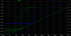
I take this to mean BW, since for any CCS I design DC impedance is the same as say, 1KHz impedance. Well, I've concocted two CCS's and posted the simulated AC response. Which one do you say has better bandwidth? Don't they technically have the same bandwidth, just diffeent impedance? If the blue trace rolled off at 100KHz but had a comparatively inferior PSRR of -117db at DC, would you consider it to be "audio quality"? Although I will mention - were this true the phase would also be flat across the audio spectrum - perhaps it is phase that matters more than DC or AC response? Not suggesting anything, just thinking out loud. [EDIT: I just went back and reread that post, I realize this isn't really an appropriate response but I'll leave it in anyways for your interest/entertainment]
Also, why can't we just add a resistor in series with the CCS? This would help damp ringing/high-Q peaking, and might allow us to use faster, lower voltage devices with low Cob such as the 2N5089 (5210 has higher voltage, same Cob) or company.
For interest I've also attached a PDF about a type of CCS that mitigates the effects of Cob, possibly of interest - and a modification of it to boost performance of a cascode. The PNP buffer before the cascode reroutes any current from Cob back to the cascode's emitter, so it hits a dead end. This also greatly reduces Early affect (as on Hfe and thus Ib, which is also rerouted just as described above), as seen on the DC impedance. The solution is also automatically temperature compensated, so we don't need to worry about using LEDs or diodes for biasing. R3 will decrease PSRR for rails - but we can split in two and tap with a capacitor to ground, filtering out any rail interference. This is especially effective with tube rails, since high voltages allow us to use a very large top resistor.
Might post more if it comes to mind.
- keantoken
??
approximately... said:what matters in a CCS is AC impedance
I take this to mean BW, since for any CCS I design DC impedance is the same as say, 1KHz impedance. Well, I've concocted two CCS's and posted the simulated AC response. Which one do you say has better bandwidth? Don't they technically have the same bandwidth, just diffeent impedance? If the blue trace rolled off at 100KHz but had a comparatively inferior PSRR of -117db at DC, would you consider it to be "audio quality"? Although I will mention - were this true the phase would also be flat across the audio spectrum - perhaps it is phase that matters more than DC or AC response? Not suggesting anything, just thinking out loud. [EDIT: I just went back and reread that post, I realize this isn't really an appropriate response but I'll leave it in anyways for your interest/entertainment]
Also, why can't we just add a resistor in series with the CCS? This would help damp ringing/high-Q peaking, and might allow us to use faster, lower voltage devices with low Cob such as the 2N5089 (5210 has higher voltage, same Cob) or company.
For interest I've also attached a PDF about a type of CCS that mitigates the effects of Cob, possibly of interest - and a modification of it to boost performance of a cascode. The PNP buffer before the cascode reroutes any current from Cob back to the cascode's emitter, so it hits a dead end. This also greatly reduces Early affect (as on Hfe and thus Ib, which is also rerouted just as described above), as seen on the DC impedance. The solution is also automatically temperature compensated, so we don't need to worry about using LEDs or diodes for biasing. R3 will decrease PSRR for rails - but we can split in two and tap with a capacitor to ground, filtering out any rail interference. This is especially effective with tube rails, since high voltages allow us to use a very large top resistor.
Might post more if it comes to mind.
- keantoken
Attachments
- Status
- Not open for further replies.
- Home
- Amplifiers
- Tubes / Valves
- SS CCS and distortion