
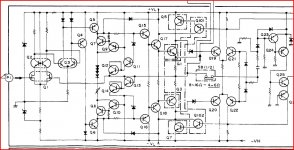
obviously from some japanese amplifier usualy cricuits like that rock !!! very simple to make if done properly ( done properly means proper pcb proper filtering proper arangements and good quality parts )
please notice that comercial japanese amplifiers even though builted with none of the above units as amplifiers only performed very very nice.......
as a device though often suffered from a number of problems such is bad preamps ,bad crosstalk figures , bad cable routing , marginal power supply and transformer ....
let us not forget that this was comercial amps of the 1980... so using the old circuit and improove the above will make a very nice amp almost on the high end side
one draw back is the double diode of the VBE multiplier which i think will be impossible to find so either you have to create a string of diodes with a couple of 1N4148 or convert the schematic in order to use a transistor as a sensor
input fet might be tricky and be sure that the amplifier is based on the specific fets to work properly replacing those with something else and things are going to change ....for good for worst dont know .... but change ..
regards sakis
Last edited:
I think I would drop the front LTP, cascode the second to up transconductance and thats it, a two stage amp, that is if you see a folded cascode amp as a single stage. Ive actually got a amp which is exactly what I described, same than that schematic but for better mirror and without front ltp. Its super fast and the result is 20 khz distortion is virtually the same as that at 1 khz or 100hz, and is very low distortion , better than D self circuits.
Last edited:
Reminds me of a Pioneer A80 i used to have,
😱 That pioneer has too many parts for my liking.
😱 That pioneer has too many parts for my liking.
And that's just the block diagram 😉 Ever seen the full circuit, full manual is on here,
User account | HiFi Engine
Bought it in the 80's on the basis of specs, and before I knew what really made a good amp sonically, and while it was for the day a top class performer it always sounded a little cold. You soon tired of listening to it somehow, despite it's technical excellence. A JLH 10 watter would see it off sonically without any trouble whatsoever.
Do you know what language all that is in ??? I would like to take a look at that site, some interesting stuff there.
The last two designs you showed are very good, they can have excellent sound quality, the third should be simplified, using 3 jfets like that is crazy, just use one 2sk170 and one 2sj74. The second schematic should also see be simplified, no need for all those current mirrors, look at nad latest amps, cyrus models from 3 up, myryad, accuphase and the latest marantz top models for implementations of those kind of designs.
two more
Those I wont comment on, never built anything with that topology, maybe someone else has experience with it.
re
The last amp is easy and cheap to build...maybe make this and take an conclussion.
no much power
The last amp is easy and cheap to build...maybe make this and take an conclussion.
no much power
Sorry... bit off topic I know,
I'm fascinated by some of these... such as the above and the obsession with visual symmetry in circuit design.
I'm fascinated by some of these... such as the above and the obsession with visual symmetry in circuit design.
Why do some call it a obsession???? ......., some say they dont use any symmetry in their designs and yet they have push pull outputs which is symmetrical, Mooly if Im not mistaken your mosfet design also has symmetrical push pull output. It has nothing to do with visual symmetry but with improved parameters, such as slew rate and many other benefits. If you so against symmetry why didnt you use a assymetrical output stage for that part of the amp too, something like a transistor biased by a current source.
- Status
- Not open for further replies.
- Home
- Amplifiers
- Solid State
- build this or not ??