Transistor pads
For anyone building this amp, here's a source for some really good transistor isolation pads:
http://www.diyaudio.com/forums/vend...-83-isolators-247-1-ea-stock.html#post2174207
For anyone building this amp, here's a source for some really good transistor isolation pads:
http://www.diyaudio.com/forums/vend...-83-isolators-247-1-ea-stock.html#post2174207
Very nice Andrew!
You're the man! 😀
Delta T is critical here in Brazil, because average ambient temperature can be sometimes very high (in summer it can get as hot as 42ºC). Despite that, when it's hot we use air conditioner, so this is not a big issue - temparature is somewhat controlled and won't be higher than 25ºC in my listening room.
Here's the info provided by the manufacturer of the HS15560 heatsink. I put the 2 options that were considered:
Thank you again for all the good info.
You're the man! 😀
Delta T is critical here in Brazil, because average ambient temperature can be sometimes very high (in summer it can get as hot as 42ºC). Despite that, when it's hot we use air conditioner, so this is not a big issue - temparature is somewhat controlled and won't be higher than 25ºC in my listening room.
Here's the info provided by the manufacturer of the HS15560 heatsink. I put the 2 options that were considered:
An externally hosted image should be here but it was not working when we last tested it.
Thank you again for all the good info.
Cloning the clone?
At an eBay store near you... 😱
Diy super leach clone (double barrel) power amp pcb set - eBay (item 280495327394 end time May-18-10 20:41:38 PDT)
At an eBay store near you... 😱
Diy super leach clone (double barrel) power amp pcb set - eBay (item 280495327394 end time May-18-10 20:41:38 PDT)
Cloning the clone ...
How sad. It looks to be a very poorly done copy. They even misrepresent what it is! They call it a 'double barrel' Leach which we all know is an entirely different animal.
Bummer ...
How sad. It looks to be a very poorly done copy. They even misrepresent what it is! They call it a 'double barrel' Leach which we all know is an entirely different animal.
Bummer ...
I wonder if the ebay clone has the feedback loop installed. Copying others work seems to be something common these days. And we begin to wonder why more good amp layouts are not found for us diyers these days.
I would like to know how much Dr. Leach is getting for each of these sold. At 55.00 each they are clearing an easy 25. Not bad for an ebay add and mailing address.
Tad
I would like to know how much Dr. Leach is getting for each of these sold. At 55.00 each they are clearing an easy 25. Not bad for an ebay add and mailing address.
Tad
this is probably a stupid question....can the Leach Amp be built on breadboard or do i absolutely need a pcb board?
I think that too much parts - easy to make mistakes. and the stability and safety problem ...I myself just now soldering a classic Leach 4.5 amp for active sub-woofer.
ok thanks. i figured it wouldn't be safe...how much current can a breadboard handle?
i emailed mr. leach 2 weeks about a pcb board but haven't gotten a reply. i really want to build it and i've never made a pcb myself either.
i emailed mr. leach 2 weeks about a pcb board but haven't gotten a reply. i really want to build it and i've never made a pcb myself either.
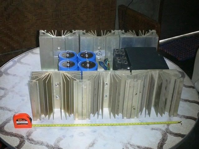
Tony,
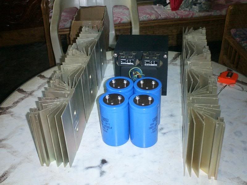
Did you get a deal on those caps? 100 volt is not cheap.
Dub, I have a few Leach amp boards in the 10 trasistor version that you are welcome to buy. They have the output transitors on the pcb and you will not have to run wire all over the place like on Dr. Leach's board. Send me an email with your full name, email address, and mailing address. These are left over from the previous group buy.
Tad
Hi Guys,
just been looking at the BOM again and have some questions.
1./ Why is the input cap 470uF, this seems really high for an imput cap, generally they are 2-5uF. If I have to go really high is 100uF bipolar high enough, I have some in stock?
2./ Would 100uF 16V work in the position of C15, its speced at 470uF 16V but would use what I have on hand if its alright?
3./ C4 and C22 have no value, any ideas?
4./ I recall Andrew telling me that I need 24mV across the emitter resistors for stability. I did some calcs and to get this thing idling at 240Watt Class A with 80V rails, I need 0.1 ohm resistors, these seem really low. Does any one think this is too low?
use Cordell's stability formula to check that these devices can be used at this high voltage level with a low value Re.4./ I recall Andrew telling me that I need 24mV across the emitter resistors for stability. I did some calcs and to get this thing idling at 240Watt Class A with 80V rails, I need 0.1 ohm resistors, these seem really low. Does any one think this is too low?
I doubt you can go anywhere near as low as you have suggested on +-80Vdc.
Sorry for offtopic:
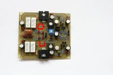
I completed Leach amp 4.5 assembly for active subwoofer.
I have some doubts about small resistors are shown in attached picture.
These 10ohm metal film Vishy resistors according to the specification is 1/2w, but they are smaller than the standard 1/4w resistors. Are these little appropriate or should i replace them with bigger? Maybe someone has experience with them? Thank you.
Attachments
use Cordell's stability formula to check that these devices can be used at this high voltage level with a low value Re.
I doubt you can go anywhere near as low as you have suggested on +-80Vdc.
Thanks Andrew, I take it I can find this formula on the forum? But it doesnt seem to make sense, if i follow the golden rule to keep the amp stable the resistor value goes low. If the resistor value is too low then the amp becomes unstable🙂
If I remember rightly, the aleph 2 uses 1 ohm and is stable, but this would not follow cordells rule would it? Am I missing something or does it not apply to fet amps?
Cordell discusses it in detail in his interview thread.
BTW,
the internal emitter resistance also drops a bit of voltage.
As the external Re takes on lower values the Vre becomes lower as well.
Many have found that optimum Vre of 18mV to 20mV when Re=0r1.
Leach used 0r33, I suspect you will need to stay around this value for +-80Vdc. It depends very much on Rth j-C and Rth c-s and transistor gain. These are dependent on the device and insulator chosen as well as the chosen voltage.
Luke,
can you refer to the posts that have the latest schematic and the latest BOM?
Last edited:
what is the dissipation for the 10r resistors?I have some doubts about small resistors are shown in attached picture.
These 10ohm metal film Vishy resistors according to the specification is 1/2w, but they are smaller than the standard 1/4w resistors.
There is a Leach enquiry thread.
Cordell discusses it in detail in his interview thread.
BTW,
the internal emitter resistance also drops a bit of voltage.
As the external Re takes on lower values the Vre becomes lower as well.
Many have found that optimum Vre of 18mV to 20mV when Re=0r1.
Leach used 0r33, I suspect you will need to stay around this value for +-80Vdc. It depends very much on Rth j-C and Rth c-s and transistor gain. These are dependent on the device and insulator chosen as well as the chosen voltage.
Luke,
can you refer to the posts that have the latest schematic and the latest BOM?
I need to do some reading on this topic.
The parts I have quoted are from the latest BOM and schematic.
- Status
- Not open for further replies.
- Home
- Group Buys
- Leach Amp pcb group buy interest