You may also wish to put your OPT's to the back of the chassis. Keep them away from the output tubes as much as practical.
I thought that too near the power transformer would cause more problems, no?
You can decouple the OPT from the PT by orientation. Not uncommon to have PT and OPT together but rotated 90 degrees. Certainly it helps to have them apart as well. I would rather have the trannies close and decoupled than have the OPT and tubes too close together. MJ talks about it in his book as well.
You can decouple the OPT from the PT by orientation. Not uncommon to have PT and OPT together but rotated 90 degrees. Certainly it helps to have them apart as well. I would rather have the trannies close and decoupled than have the OPT and tubes too close together. MJ talks about it in his book as well.
Better?
Attachments
")
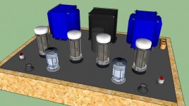
Hmm, is the sketchup model to scale? Looks like the transformers are very small compared to the tubes and RCA inputs...
Are they dual volume pots? I would have thought it would be easier to have a stereo volume pot. Messing with two volumes would be a pain in the neck for me.
Enjoy the build!
Are they dual volume pots? I would have thought it would be easier to have a stereo volume pot. Messing with two volumes would be a pain in the neck for me.
Enjoy the build!
Hmm, is the sketchup model to scale? Looks like the transformers are very small compared to the tubes and RCA inputs...
Are they dual volume pots? I would have thought it would be easier to have a stereo volume pot. Messing with two volumes would be a pain in the neck for me.
Enjoy the build!
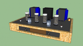
You're right about the scale... I pulled the tube setup from another SketchUp model and assumed the scale would translate. Attached is the re-scale.
I have always used two volume knobs since I'm paranoid that the pot sections will somehow imbalanced and I'll live my life with one channel louder than the other.
No science here. Strictly paranoia.
Kofi
Attachments
Last edited:
I had installed two mono stepped attenuators on my simple se at one point and hated every minute of it. It was the biggest pain, so I switched to stereo. I would reconsider if I were you.Are they dual volume pots? I would have thought it would be easier to have a stereo volume pot. Messing with two volumes would be a pain in the neck for me.
I never had a problem with it. In fact not having some kind of balance contro I would consider a design flaw.I had installed two mono stepped attenuators on my simple se at one point and hated every minute of it. It was the biggest pain, so I switched to stereo. I would reconsider if I were you.
You're right about the scale... I pulled the tube setup from another SketchUp model and assumed the scale would translate. Attached is the re-scale.
Kofi,
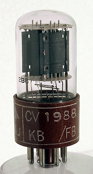
They still dosn't look right. Not the size, but the proportion. You look to have scopped up some 8-pin tubes, not 9-pin ones.
The amp looks to be 6SN7 driving EL34, not ECC83 driving EL84.
dave
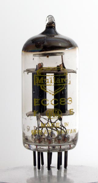
I know the tubes are wrong, but these were the only reasonably similar tube models that were immediately available in SketchUp models.
It wasn't hard to find this "12AX7/ECC83", it could be stretched vertically to become an EL84
dave
Attachments
Kofi,
Only just come across this thread.
Since the original Baby Huey was posted I have built about 5 more with all sorts of variations.
The original one that you posted on page 1 is the simplest and cheapest. The one I liked the best was a fixed biased, mosfet follower, 6SL7 + 6V6 version with tube rectifier (5R4) and choke input supplies to polypropylene power supply caps.
However:
While working on some updates to my latest BH I have been running the original prototype on my system (your page 1 schematics). I also spent the last 3 weeks upgrading and tweaking to the limit, a friends Music Angel 845 SET. When he came around to pick up the 845 last weekend we had a good listen to it then unplugged it and put the original Baby Huey back in the system. His crestfallen expression when he heard the Baby Huey after a half hour session on his 845 SET was priceless - The Baby Huey was simply better.
The Fixed bias version with the mosfet followers to drive the output tubes is better again but you sacrifice the simplicity and the no adjustment required philosophy of the original.
As the BH has effectively only a single power supply, it is worth noting some of the advise above and get that power supply as good as you can. Where a bad supply shows up is in the intermodulation distortion products between the signal and any power supply ripple. If there is very little ripple then there will be very little in the way of these intermodulation products. There was a mod about half way through the BH Thread (Allen Wright PPC inspired) where instead of returning the 2 cathode CCS bypass caps to 0V, the 0V ends of the caps are tied together and then a resistor is used from that point to 0V. I have this mod in my original BH and find that (for EL84 Outputs tubes) a value of 39 Ohms works well. This mod reduces odd harmonic distortion a little but seems to reduce intermodulation distortion a hell of a lot. Something for you to try.
Best of luck with your build.
Cheers,
Ian
Second Ian's note on the cathode bypass. Ian's original thread prompted me to try it. It worked very nicely on my amp:
http://www.diyaudio.com/forums/tubes-valves/72536-el84-amp-baby-huey-46.html#post1498232
Sheldon
http://www.diyaudio.com/forums/tubes-valves/72536-el84-amp-baby-huey-46.html#post1498232
Sheldon
Re volume control pots.
You could consider 2 mono pots spaced closely either side of an idler wheel. Turning either knob will drive the other yet still allow slippage for fine control.
I used a tuning spindle and bearing from an old table radio then super glued 2 O'rings onto a screw-on toothepaste cap. Us DIYers can do these things.
Or neater would be to use knobs with a larger diameter than the pots themselves and simply let one drive the other via O'ring friction. Just remember to reverse connections on one of them.
Charles
When he came around to pick up the 845 last weekend we had a good listen to it then unplugged it and put the original Baby Huey back in the system. His crestfallen expression when he heard the Baby Huey after a half hour session on his 845 SET was priceless - The Baby Huey was simply better.
So there, to all you SE lovers - P-P (done right) isn't the glugfest you believe it to be.
Well done, Ian!
Regards, Allen
Kofi,
Only just come across this thread.
Since the original Baby Huey was posted I have built about 5 more with all sorts of variations.
The original one that you posted on page 1 is the simplest and cheapest. The one I liked the best was a fixed biased, mosfet follower, 6SL7 + 6V6 version with tube rectifier (5R4) and choke input supplies to polypropylene power supply caps.
However:
While working on some updates to my latest BH I have been running the original prototype on my system (your page 1 schematics). I also spent the last 3 weeks upgrading and tweaking to the limit, a friends Music Angel 845 SET. When he came around to pick up the 845 last weekend we had a good listen to it then unplugged it and put the original Baby Huey back in the system. His crestfallen expression when he heard the Baby Huey after a half hour session on his 845 SET was priceless - The Baby Huey was simply better.
The Fixed bias version with the mosfet followers to drive the output tubes is better again but you sacrifice the simplicity and the no adjustment required philosophy of the original.
As the BH has effectively only a single power supply, it is worth noting some of the advise above and get that power supply as good as you can. Where a bad supply shows up is in the intermodulation distortion products between the signal and any power supply ripple. If there is very little ripple then there will be very little in the way of these intermodulation products. There was a mod about half way through the BH Thread (Allen Wright PPC inspired) where instead of returning the 2 cathode CCS bypass caps to 0V, the 0V ends of the caps are tied together and then a resistor is used from that point to 0V. I have this mod in my original BH and find that (for EL84 Outputs tubes) a value of 39 Ohms works well. This mod reduces odd harmonic distortion a little but seems to reduce intermodulation distortion a hell of a lot. Something for you to try.
Best of luck with your build.
Cheers,
Ian
Thanks for responding! I was hoping I could rope you in to the discussion.
Glad to hear that the BH was so well received by your SET friend. I enjoy both topologies but have been mostly SET in recent years.
For this build, I will have to do without the fixed bias as the recipient is not electronically inclined. I will, however, implement this in my build once I am complete with his...
As far as the cathode bypass caps are concerned, I'm thinking you're talking about the 100uF / .22uF combo off the EL84s, correct? If so, I'll gladly give the 39R resistor a try. If I'm wrong about the caps you're talking about, please let me know.
Thanks for this design. I'll be ordering parts this week and I'll keep the forum updated with my build.
Kofi
- Status
- This old topic is closed. If you want to reopen this topic, contact a moderator using the "Report Post" button.
- Home
- Amplifiers
- Tubes / Valves
- Kofi Annan in: "Kofi's Baby Huey"