Linear array in a normal listening room
In a normal listening room there are two (probably) parallel planes: floor and ceiling. That is the reason why a curved array would not be optimal. I would try a linear array starting from floor and continuing at uniform (short) intervals until the ceiling ends it. A round cross section of the tubular enclosure would minimize diffractions of the sound waves. I would not expect or want much the sideward directivity because I don't allways sit in one point listening music. If I did so, I would probably use earphones.
In fact I like earphones and usually use them if I want extreme accuracy while editing some sound samples, etc. But when I listen to music, I relax and want to move freely. Then the sideward directivity would be a disadvantage.
Somewhat like the DBX Soundfield?
http://www.renatogiussani.it/images/Ste_Perc/pag66_1.jpg
Similar, but I'm thinking a 3" square cross-section. Make it roughly 2 feet long. 25 drivers on each of the 4 sides.
Chris
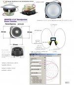
anybody have an actual freq resp curve for those drivers??
didn't see it on PE's site...
thanks
_-_-bear
didn't see it on PE's site...
thanks
_-_-bear
on the other hand concave would result in theoretically better sound in the sweet spot, less smear in time domain, and no smear in the exact focus point but at the price of making the spot even smaller
what about 2 cylindrical/elliptical columns, around 5" or maybe more in radius, joined at their edges. when viewed from above would resemble a sideways figure of eight shape. then insert drivers into the sides of the horn 'flare' as near to the mouth as practicable, 50 on each side. like a linear, horned array...if you will excuse my poor description
in case you dont understand heres a quick slapdash drawing as i have just finished a night shift...:
An externally hosted image should be here but it was not working when we last tested it.
could even be turned into a bipole horn array if so inclined.....or maybe its a ripole horn array....who knows? if i had so many 2" drivers, this is what i would try.
good luck and have fun.
Last edited:
what about 2 cylindrical/elliptical columns, around 5" or maybe more in radius, joined at their edges. when viewed from above would resemble a sideways figure of eight shape. then insert drivers into the sides of the horn 'flare' as near to the mouth as practicable, 50 on each side. like a linear, horned array...if you will excuse my poor description
in case you dont understand heres a quick slapdash drawing as i have just finished a night shift...:
..could even be turned into a bipole horn array if so inclined.....or maybe its a ripole horn array....who knows? if i had so many 2" drivers, this is what i would try.
good luck and have fun.
Hi Bear,
Good ideas, 🙂 See my pictures:
b
Ps. b = bjorno= Björn in Swedish = bear
Attachments

Spherical Array
An externally hosted image should be here but it was not working when we last tested it.
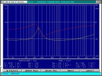
bjorno bear, the eliptical baffle will have significant effect as a horn/wavguide thingie and will need to be measured, I think it will prove to have boost where you don't want or need it.
graff we see/hear things differently?
😀
_-_-bear
graff we see/hear things differently?
😀
_-_-bear
graff we see/hear things differently?
How can I know? 🙂
I am not at all sure what You suggest, You want me out of this thread or what?
I am not fanatical follower of the KISS principle but with so many drivers which mean a lot of work anyway it's good to start with
feel free to express different opinion
best regards,
graaf
bjorno bear, the eliptical baffle will have significant effect as a horn/wavguide thingie and will need to be measured, I think it will prove to have boost where you don't want or need it.
_-_-bear
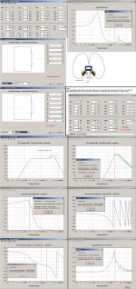
Agree,Here is proof showing you need to filter but the result can IMO be good if tweeked out. 🙂
b
Attachments
Another vote for spherical array
Hi, Ben:
I'm jumping in a bit late here - was hesitant to suggest a quasi-spherical array, being unsure if the omni-directional concept had fallen out of favour. But since other members have also suggested it, I dug up this copy of an old article in support of the idea. What do you think? The carpentry could indeed become a bit tedious. If I were you, I'd start with just a pair of these, leaving ample drivers left over to build other designs for comparison.
Regards,
Wilf
Attachments
Drivers should arrive Monday, getting excited!!!
That Dodecapentagon looks interesting.
I might have to order more drivers and build one of each suggestion and compare them all.
That Dodecapentagon looks interesting.
I might have to order more drivers and build one of each suggestion and compare them all.
Last edited:
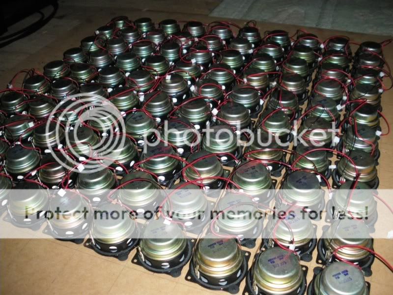
Not 2 mins after my previous post the courier arrived with a crapload of drivers 😀
pics to come.
pics to come.
Only 1 box arrived today, I get the rest on Monday.
They were poorly packaged and 4 were damaged.
Here's 5x7 in their tray
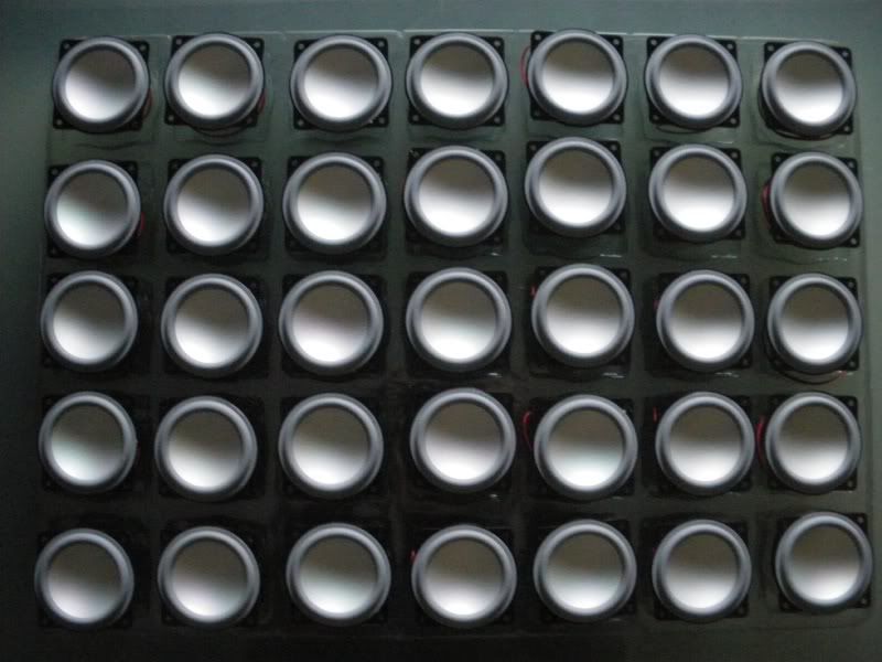
10x10 really is a lot of drivers isn't it? lol
They were poorly packaged and 4 were damaged.
Here's 5x7 in their tray
10x10 really is a lot of drivers isn't it? lol
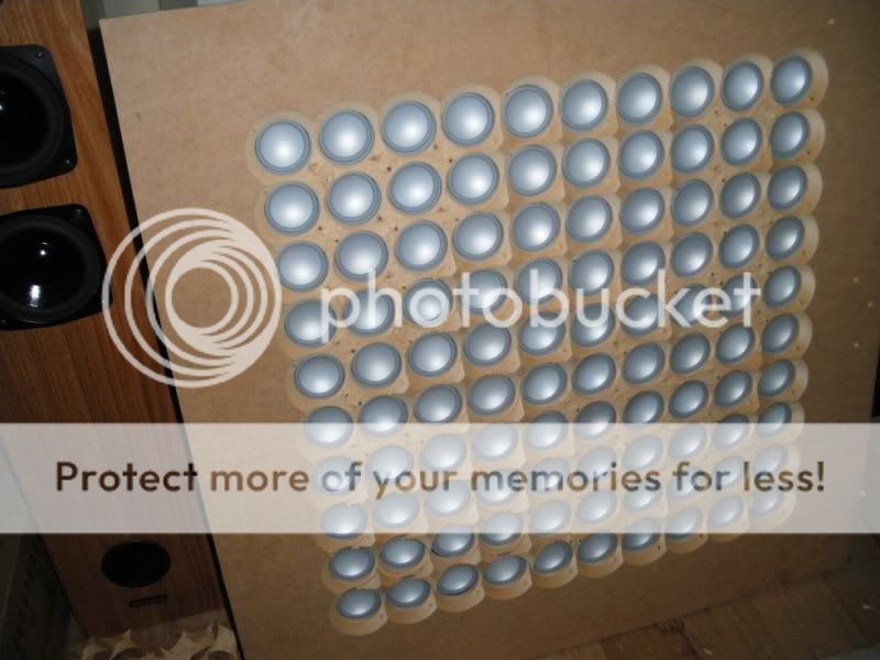
graff, the problem I have is that a wide N x N sized array always has known characteristics that get worse with rising frequency - so why do it??
It's been done, investigated and explored.
You can go back to find Dr. Bose's original work, you'll see that he ended up making a corner into a spherical surface (at least he did that) with multiple drivers.
The problem is that with rising frequency the driver becomes more directional, so you get awful effects that vary with frequency when you make an array that is N x N wide.
Ok, you like it... and you seem to push ur ideas strongly, not much more to be said about it then?
Only my opinion...
_-_-bear
Last edited:
Agree,Here is proof showing you need to filter but the result can IMO be good if tweeked out. 🙂
b
What you have is a bit reminiscent of that conical horn with the cone drivers tapped in at 1/4 wave from the tail end where there is a HF compression driver, the name escapes my swiss cheeze brain at the moment. Geez.
Or a little like some of the pro sound vertical array cabinets that have some sort of compression or ribbon driver at the tail of a "V" with two mids left and right...on the "V"...
I think I would go for a wider baffle, a gentle curve to the mids, left and right, less "waveguide/horn" effect (or none)... a big smooth transition at edges is a great idea especially for drivers like these that go high in frequency...
again, only my opinions.
_-_-bear
bjorno bear, the eliptical baffle will have significant effect as a horn/wavguide thingie
THAT was the purpose of my post....sizes for optimum performance would need to be calculated, but the horn/waveguide loading of this many drivers would hardly be a bad thing, if done correctly. If gain could be had down to say 200-500Hz then a large high efficiency woofer (15" alpha?) on OB, similar to the MJK type, and crossed to the waveguided focussed array, COULD be very good regarding wide band CD operation. At least that is what i would believe. Gedlee would be the one to ask on this i would think.
Your dimensions are WAY too small to work at 200Hz, or even 500Hz.
take a look around at the physical size of horns or "waveguides" that work at the frequencies you're interested in, and you'll see what size you need.
There would be no benefit whatsoever unless the driver you selected basically rolls off below some point around say 3-4kHz, so then the "horn" loading would bring up the lower response - otherwise you'll have to throw away the gain you get to get a flat response.
Why do you want "CD" (a really bad term - do we mean Constant Directivity or Constant Dispersion, geez... and what does that really mean - I hate those terrible terms, so non descriptive!!) in the first place? By making a line source, you already have very uniform dispersion in the horizontal plane at frequencies below the point where the wavelength starts to get close to the inter driver dimension and the driver's size... all you have to cope with the xover point you pick and then the highs... which in reality is not a big deal when you go to listen to a line source.
_-_-bear
Your dimensions are WAY too small to work at 200Hz, or even 500Hz.
yes i know....it was a rough idea. no calcs done. that would be for the OP to do......still it COULD be done.
take a look around at the physical size of horns or "waveguides" that work at the frequencies you're interested in, and you'll see what size you need.
There would be no benefit whatsoever unless the driver you selected basically rolls off below some point around say 3-4kHz, so then the "horn" loading would bring up the lower response - otherwise you'll have to throw away the gain you get to get a flat response.
preaching to the choir here im afraid.
Why do you want "CD" (a really bad term - do we mean Constant Directivity or Constant Dispersion, geez... and what does that really mean - I hate those terrible terms, so non descriptive!!) in the first place?
i agree it is a bad term, but thats the terminology, for all its faults. Limited dispersion would be better, or sub quadrant radiation would be better. VER and all that stuff that wouldnt benefit anyone.....😕
By making a line source, you already have very uniform dispersion in the horizontal plane at frequencies below the point where the wavelength starts to get close to the inter driver dimension and the driver's size... all you have to cope with the xover point you pick and then the highs... which in reality is not a big deal when you go to listen to a line source.
correct. wide dispersion in horizontal plane, limited dispersion in the vertical plane. arrays have advantages like ALL loading methods. and disadvantages. like combing in the vertical plane in a line array, and just general combing in both planes in a n x n array.
depending on t/s a horn loading a metre long from the apex of the horn, and 2m high x 1 metre wide would give fairly good lower midrange Gain, though not to 200Hz, with a little (read alot less than with an array) judicious EQ boost the roll off could be assisted. but thats up the the OP to decide.
peace
- Status
- Not open for further replies.
- Home
- Loudspeakers
- Full Range
- 200 x 2" drivers What to do?