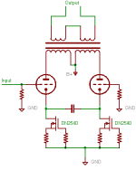
My heading pretty much sums up my question, but here's the details :
PP triode strapped pentode/tetrode tubes
parallel tubes (a quad per channel)
LM317 run as CCS in cathode of EACH tube
If the point of matched tubes is current draw being the same, then isn't this accomplished via the CCS supplying each tube ?
Is it more than that ? Does tube matching have to do with the individual tubes having differing amounts of gain at different current levels ?
Do I need to have matched tubes AND CCS for best performance ?
Thanks....................Blake
Great question,
In general I would say no, no need to go mad matching tubes. They are kept in class A by the CCS so you should be fine. Of course getting wildly mismatched tubes to work will be hard but you could even get two totally different types to work eg a 6L6 and an 807 (both quite similar) or even an EL34 with 6L6/807.
Matched tubes is a bit of a misnomer anyway. What did they match them with/at?....... or do they look the same? Some sellers claim they sell matched tubes but they are not matched for the parameters in your amp and wont be after several hours use.
Im a bit torn at the moment with my 6L6ish amp whether to go CCS class A or mental AB2 with bias pots for each valve. A2?
Cheers Matt.
Last edited:
I just finished the first iteration of my EL84 PP UL amp, and it has a real mixture of old power tubes. I call it the United Nations amp 🙂 The next thing I was going to do was try 317 CCS on each cathode to see what effect it has.
It worked great on a little Chinese 6P1 PP (not UL) amp, but as I don't have a tube tester I couldn't tell how mismatched the original tubes were. However, one was odd enough to go into runaway with 270 ohm cathode resistor bias if the B+ rose over the 250v tube limit.
I would love to see some other expert opinion on "flattening" tubes with CCS bias.
I don't understand the whole CCS-in-the-cathode-of-a-common-cathode-stage thing. You would want a constant voltage there. If you put in the cathode a true CCS (CCS behavior over the entire audio band), then the cathode voltage will just 'track' the grid voltage. Ugk and Ip remain the same, so the AC plate voltage will be the same as the AC grid voltage The end result is a stage with unity amplification, a "plate follower" as it were.
Can someone, please, enlighten me or tell me what is wrong in my above deduction? Or is it the point that we must use CCSes which are CCS for DC only and bypassed for AC?
Thanks
Kenneth
Can someone, please, enlighten me or tell me what is wrong in my above deduction? Or is it the point that we must use CCSes which are CCS for DC only and bypassed for AC?
Thanks
Kenneth
CCS is usefull for when you have a differential pair amplifier..
The CCS idealy is for DC biasing purpose...but should idealy be as high impedance as possible, as if it weren't there...otherwise, it would act as an AC load which would be not ideal...
The differential coupling takes place in the tail....the follower output will drive the cathode of the other side...you want ALL the AC current to be used to drive the other side of the pair....if the CCS has low impedance it will shunt some of this AC current making a current divider, thus diminishing good AC coupling of the differential halves... Throw in some parasitics such as the CCS capacitance and you can see the high frequency pole introduced...
Having a CCS does not gaurantee or improve matching... The tubes still need to be AC matched for transconductance....A CCS will help in stabilizing the gm in that it reduces this variable's dispersion...
Chris
Chris, yes but this is not about a long tailed pair with a common CCS, it is about a CCS in the cathode of every tube...
Can someone, please, enlighten me or tell me what is wrong in my above deduction? Or is it the point that we must use CCSes which are CCS for DC only and bypassed for AC?
There is nothing wrong with your reasoning. As I pointed out in another thread this is plain silly: CCS should easily have impedance in the megaohm range, right ? That just doesn't fit the U = R * I at required U for desired I for any sane combination of the two. Once bypassed, it is just a weird way of stabilizing voltage (bias).
If there was a real CCS in cathode part of the circuit and the output is taken from the anode, the amplifier wouldn't work, just as you pointed out.
In that case the CCS is bypassed with a cap, so it only controls the idle current, in which case you would still need matched valves for best performance.it is about a CCS in the cathode of every tube...
Thank you , gentlemen !
I AM in fact talking about a differentially loaded (self phase splitting) output run Class A. Sorry I forgot to mention that.
What I am gathering from this is that if I use a single CCS in the tail, un-bypassed , that the tubes need not be matched if they are a new run from a single manufacturer , presumably close manufactured runs/tolerance ? This is because ALL current , AC or DC is loaded through the CCS ?
If I were to use a CCS in each tail, this would set DC bias/idle current only, and the bypass cap allows for AC current . In this case I would be better off to use a matched set that is matched for transconductance and not just idle current ?
Do I seem to have the gist of this ?
......................Blake
If your refering to Class A P-P pair with a CCS in the tail... Then theoretically you do not need any AC bypass if you have perfect gm matched pair... This is because the AC currents, if perfectly matched, are 180 degrees of each other and would perfectly cancel.... This would leave a net of ZERO AC current in the tail... Since we do not have perfect matching, there will be degeneration associated with the AC imbalance...this is why a bypass cap my be added..
If it is a diff pair using one input such as a phase inverter, then you don't bypass, since any bypass will diminish the coupling that is critical...
Chris
If it is a diff pair using one input such as a phase inverter, then you don't bypass, since any bypass will diminish the coupling that is critical...
Chris
A CCS in the cathodes of a differential pair is the correct way to do it.
BUT - you need some control over the individual tube's grid voltage to ensure both are running at the same current = zero offset current in your OPT.
CCS's in the cathode of each tube will give you zero gain, not x1, so each would need a big cathode bypass cap to work.
Regards, Allen
BUT - you need some control over the individual tube's grid voltage to ensure both are running at the same current = zero offset current in your OPT.
CCS's in the cathode of each tube will give you zero gain, not x1, so each would need a big cathode bypass cap to work.
Regards, Allen
The worst of my TV video tubes have succumbed to the CCS.What I thought were hopelessly mismatched-hullouts have a new lease of life.
The cathode of a Williamson diff driver and LTP is the perfect place. However, one can overdo-it if the anode load also has a CCS fitted, lacking damping a high gm tube will oscillate gracefully and a pain to cure.
richy
The cathode of a Williamson diff driver and LTP is the perfect place. However, one can overdo-it if the anode load also has a CCS fitted, lacking damping a high gm tube will oscillate gracefully and a pain to cure.
richy
Not exactly the question, but I did try a 317 in the cathode of a EL84 amp and I really hated the sound - put a resistor back ASAP.
Andy
Andy
What you are describing as your configuration is exactly what I have in all of my amps. The reason is because i use toroidal output transformers in all my amps and they will not tolerate DC imbalance. It was this that has dictated my choice here, not the desire for Constant current..
Having said that it has worked really well, it keeps everything stable on my 6AS7 amp until the mismatch is such that the finals go into oscillation. No adjustment is needed throughout service.
The way I do it is to bypass each cathode with a 1000uf cap and instead of referencing the cathode to earth, I tie them together and reference the node created to earth via a 1meg resistor. This forces all AC signal to travel through the back to back caps and so gives perfect differential performance. If you tie the node straight to earth then the differential performance is compromised. Others, such as Allen Wright, have tried similar things but have used a 300R resistor to bleed off AC error signal at the node. They claim this behaves better as things approach class B. Personally my experience is that with the 1meg it sounds tighter and cleaner, and with the 300R it sounds a bit fatter and fuller.
I am currently listening to an amp (as I type) which uses PL84 in shade configuration (6AU6 driver) and self splitter using the configuration described above.It works far better than I could ever have imagined.
My last two amps used the same output configuration but in direct coupled amps. This is a fantastic approach as the CCS will automatically adjust to create the correct cathode to grid bias over a wide range. This means that DC imbalance in the output stage will self adjust and DC imbalance in the input stage will also self adjust. It makes correct implementation of a direct coupled amp an absolute cinch.
I have heard it argued that with conventional EI transformers it is better to run them slightly in saturation in order to avoid hysteresis at crossover. The advantage of toroidals is that this is a none problem and low level reproduction is on a par with SE type transformers..
I would never advocate using tail CCS in anything but PP designs.
Hope that helps.
Shoog
Last edited:
Here's what you need to do for the self-balancing circuit others have described.
For DC, each CCS controls it's individual current. Guarantees matched current.
For AC, the 2 CCS are forced to act like a single CCS to maintain a constant total tail current during signal excursions, driving the cathode of the righthand tube to accomplish the inversion.
Also, I don't believe for a nanosecond that deliberately introducing DC offset to any OPT improves the sound. My experience is the exact opposite. Even for slightly gapped cores as in PP OPTs, you are better off with good DC balance.
Cheers,
Michael
Attachments
Shoog and Michael Koster,
What are the pro's/cons of the different ways you guys AC couple the cathodes ?
This is not intended to start a war. I think I see advantages to both designs, just wondering if I got it right.
What are the pro's/cons of the different ways you guys AC couple the cathodes ?
This is not intended to start a war. I think I see advantages to both designs, just wondering if I got it right.
There is no difference, except that Shoog describes how to abuse high
value polarized caps back to back with a bleeder. And then you would
still need a small value high quality bypass cap straight across, just as
MJK illustrates.
Cathode impedance is extremely low. It takes rather obnoxious caps
(most likely electrolytic) to couple them tightly at lowest frequencies.
Obviously also mandates the alternate parallel cap suitable for highs.
Not a battle of either/or. You really need all three caps to do it right.
Last edited:
Yes Michels is the same but finding a none polarized cap big enough is not realistic, so the back to back with a film bypass is more practical.
Despite what many may think - doing it the way I have doesn't degrade the sound. The benefits of differential performance are far in excess of any penalty in using electro caps. There is also a white paper out there somewhere which explains why back to back electro's sound better than plain electro's.
Shoog
However you do it you still have the problem that a CCS controls the average current, but you should be controlling the quiescent current. These two are only the same for a perfectly linear valve. Second-order distortion, present in all valves, increases the ratio of average/quiescent current. No problem for a small signal stage, but important in an output stage. Even traditional resistor cathode bias has to compensate to some extent for this, by running with a higher than optimum zero-signal current so the shift in bias with a signal pulls the quiescent current back nearer the correct value. Fixed bias avoids this problem. CCS bias makes it worse.
There is another problem with CCS bias. A bypassed CCS behaves at low frequencies quite differently from a bypassed resistor. This can cause LF instability if global feedback is used, and LF phase shift with no feedback. I would never use CCS bias for an output stage. If you want to match currents, then use a servo which samples at zero-crossing only.
There is another problem with CCS bias. A bypassed CCS behaves at low frequencies quite differently from a bypassed resistor. This can cause LF instability if global feedback is used, and LF phase shift with no feedback. I would never use CCS bias for an output stage. If you want to match currents, then use a servo which samples at zero-crossing only.
- Status
- Not open for further replies.
- Home
- Amplifiers
- Tubes / Valves
- Do you still need matched tubes if running a CCS ?