What amplifier you're talking about Tinitus?
This one, Fokker?
For sure....will be next step... i am already creating it...this is prototype, not to be pretty, also i am using wires...i want to see if it is stable even in a messy construction.
Boards, layout, organization, cleaning..this is something to be done after the amplifier be ready for release..for a while it is a study, an experience, changing parts, trying other subcircuits, different NFB.... watching in the scope...listening and trying other ideas...and listening again.
When ready, then i will have some friends to produce a decent board.... that board will be tested, assembled for sure..and you will be happy watching things clean.
This is not the moment dear Tinitus, i know you have not time to read all posts, you have a lot to do, but i have informed the amplifier is not ready, not realeased, that is my birthday gift, to July the sevententh...so i have time.
I am posting my experiences, pictures and schematics during the evolution of my job..to some friends that loves to follow these things..but the amplifier, for sure was not released.
I am not entirelly satisfied with it... the one to be released will be even better.... in performance..sonics...that's all matters to me...how looks..really, not my beach.
regards,
Carlos
This one, Fokker?
For sure....will be next step... i am already creating it...this is prototype
When ready, then i will have some friends to produce a decent board....
This is not the moment dear Tinitus
Carlos
Yes, what this thread is about
But I believe its exactly the right time to coinsider the final physical layout
Next time it will be too late 😉
Sorry, i cannot do that, because i may decide to remove some CCS
circuits, introduce new parts and new subcircuits...so... the layout prepared will be lost.
regards,
Carlos
circuits, introduce new parts and new subcircuits...so... the layout prepared will be lost.
regards,
Carlos
I can never do what you do
But I know a bit about design and product devellopment
"All" you need to do is "visualise" your goal, and always keep it "in sight"
That way you will get much closer to the final product
Focus on the goal, and close in on it, step by step
How to define the goal is part of it too
You could say "who cares"
I think its important
I understood what you mean...my focus, my goal is audio quality
But i have a problem...i do not trust in my evaluation...biased i am..... i do not like CCS..and this can change my evaluation.
I will invite people from my building, my friends and children to evaluate..now i have a switch to use CCS or Bootstrap
Because of this same goal, i cannot produce boards layout...because depending the evaluation others will do, i will remove CCS and install bootstrapp, and other things...also if i have to remove all CCS, the amplifier will be alike the Dx Amplifier, the standard one..then i will not release.
Will be a Dx Amplifier having super power only...so.... will not be the amplifier that received the name Fokker...then no release.
Everything depends on the audio quality, them the subcircuits will be selected this way..keeping the same topologie of course, because i love it since it appear first time fourty years ago...the sound signature is the one i like.
regards,
Carlos
Carlos, please just one small OT question, now we are here....I wont bother you further
Original Dx standard....do you know how low dc supply voltage will be work...lowest possible please ?
Original Dx standard....do you know how low dc supply voltage will be work...lowest possible please ?
I do not remember Tinitus.... please, tell me the voltage you wanna use
then i will enter the simulator and inform you if there are needed modifications or not...maybe in the bootstrapp, also in the zener series resistance.... in my imagination will work up 20 volts...but some "tuning" may be needed.
Please, do me a small favor...i will recall the Dx Amplifier thread... repeat this question there.
regards,
Carlos

The ones that wants to assemble, will have a very good amplifier
But not an awsome amplifier....better to wait to final version.
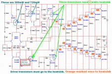
I am using CCS to the drivers (Electrocompaniet idea)....and 28 miliamperes to each driver...this means we gonna need 3 watt heatsink to each one of these CCS pass transistors.
3 watt heatsink can be made using 2 milimeters (or more, or less) thick aluminium blade, cutted in rectangle or square, then bend the way you want, produce a hole to screw and better to insulate from the heatsink... 3 centimeters side if squared may be good...but because insulator, better to make it rectangle and bend.... 3 by 4 centimeters rectangle will be better...i have these transistors installed in the main heatsink..but this will be a problem to the board layout near future..so...better solution is to let them stand over the board having it's own heatsink not to complicate the pcboard layout.
Other CCS dissipates less power..but i think they should have small blades of aluminium too, to operate warm.
The image shows these in details.
VAS must be insulated from the heatsink, a 3 watt heatsink... parasitic capacitances may bother.... heatsink having full voltage swing can be a problem..do not forget to insulate... output coil and this transistor heatsink can interact.
This one, the way it is, is very good for parties... i would like a little bit more treble (level perceived, the amplifier is flat electrically...treble quality is fine.... level is not the one i want for the trebles in my perception)
I am talking about relative level... amplifiers, even flat, have sonic signature, means bass, mids or trebles will appear to humans ear as louder....even if the speaker is flat, even the amplifier beeing flat.
Yeah..it is alike an earthquake..the deep Devil's throat vomiting the ocean abissal mountains.... perfect to powerholics, to bother neighboors or to home demolition....but needs a huge transformer..to 4 ohms 1 kilowatt transformer.... If gonna use 2 ohms, them increase transistor pairs and use 2.5 kilowatt transformer.
52 volts of output audio, rms volts will be reproduced without distortion, unclipped.
regards,
Carlos
But not an awsome amplifier....better to wait to final version.
I am using CCS to the drivers (Electrocompaniet idea)....and 28 miliamperes to each driver...this means we gonna need 3 watt heatsink to each one of these CCS pass transistors.
3 watt heatsink can be made using 2 milimeters (or more, or less) thick aluminium blade, cutted in rectangle or square, then bend the way you want, produce a hole to screw and better to insulate from the heatsink... 3 centimeters side if squared may be good...but because insulator, better to make it rectangle and bend.... 3 by 4 centimeters rectangle will be better...i have these transistors installed in the main heatsink..but this will be a problem to the board layout near future..so...better solution is to let them stand over the board having it's own heatsink not to complicate the pcboard layout.
Other CCS dissipates less power..but i think they should have small blades of aluminium too, to operate warm.
The image shows these in details.
VAS must be insulated from the heatsink, a 3 watt heatsink... parasitic capacitances may bother.... heatsink having full voltage swing can be a problem..do not forget to insulate... output coil and this transistor heatsink can interact.
This one, the way it is, is very good for parties... i would like a little bit more treble (level perceived, the amplifier is flat electrically...treble quality is fine.... level is not the one i want for the trebles in my perception)
I am talking about relative level... amplifiers, even flat, have sonic signature, means bass, mids or trebles will appear to humans ear as louder....even if the speaker is flat, even the amplifier beeing flat.
Yeah..it is alike an earthquake..the deep Devil's throat vomiting the ocean abissal mountains.... perfect to powerholics, to bother neighboors or to home demolition....but needs a huge transformer..to 4 ohms 1 kilowatt transformer.... If gonna use 2 ohms, them increase transistor pairs and use 2.5 kilowatt transformer.
52 volts of output audio, rms volts will be reproduced without distortion, unclipped.
regards,
Carlos
Attachments
Last edited:
That's what i think about so huge powered amplifiers
I think this level of power is totally unnecessary, and almost insane, say, this power bigger than 1 kilowatt at 2 ohms .. however there are those who need help alike this when playing music in big party places or open air reproduction of voice and music.
Here in Brazil there's such need .... I do not do amps for me only, I want to share, I like to see people enjoying my amplifiers and beeing happy..this is the best feeling i can have...to be helpfull, to share......I think we do not need so huge power.... for domestic use...more than 400 watts peak is too much in my point of view...seems 200 watts rms each channel...to 100 square meters place it is much more than needed, unless your speakers are not efficient.
Well...here in my country, people will build..and they will be playing inside big places...and pumping funk music at ear drum pain levels.
Do not be afraid..the amplifier is simple and generic..what complicates and makes the one crowdy are the enormous quantity of transistors because the ouput power and because of the CCS... removing these things and watching, then you will see a very simple circuit.
If you wanna a description of it's sound..the way it is today...it is sounding alike the good Sansui high power amplifiers...do you like Sansui sonics?... them will love this one...it can even beat some of them.
I will make a recording..the trouble is the power..will saturate my microphone..will try to cover it and let just a small hole to air pressure enters.
regards,
Carlos
Attachments
Last edited:
Fokker sonic signature
Sorry, microphone saturates very easy..and the supply has panels vibrating.
But you can listen..sounds very good..for a while anything special..playing using CCS to the VAS (distortion is lower)
0.005% THD of advantage...huge one isn't it?.... i think so.
YouTube - Fokker, final version will be released July.mpg
regards,
Carlos
Member
Joined 2009
Paid Member
Yes dear Bigun... this is what simulator show me....but i have not used
rail resistances to create voltage drop depending consumption...in the real world, as you know as well as i know, our voltage will drop, and we will not reach all that power...this was simulation... while using 2 ohms loads.... a transformer that rectified and filtered, provide you 90 volts each rail...will for sure reduce this voltage to 81 or less when loaded....and them, with 81 volts symetrical,you will not have 1.130 watts Rms anymore...heheheh...real things.
My transformer has enormous drop of voltage, (from 90 to 75...or even less) the transformer power seems to be not too much bigger than 700 watts...so.... more than 350 watts is hard to achieve with this power supply i am using.... transfomer power is the limiting factor..i can reduce output impedance and the result will be, always, the power the transformer can supply divided by two because the AB efficiency.
In theories, or ....in simulations...it can go to 1130 watts RMS, unclipped, over 2 ohms resistive, non inductive (not real) loads.... but this needs a huge supply, maybe a switching power supply.
Here you can see some.... i have removed the double VAS...I had troubles when using double VAS together the CCS.. the one is feeding the VAS...this always happens..happened first time i have built the Dx Blame ES...something must be wrong with my CCS... i will find others to study to see what i have different and to try other ideas... will search the web for CCS circuit variations.
YouTube - Output capacitor to ground - Fokker.avi
I am glad to see you here.
regards,
Carlos
Last edited:
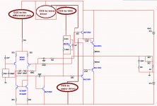
Supply voltage swing use to modulate power amplifier low signal stages
Using regulators and CCS you avoid this...or at least, the effects are greatly reduced.
Real thing is that supplies have voltage drop under consumption, at least DIY people supplies that are from Junk, from old dismounted amplifiers...when you buy a correct and honest one, then you do not need the stuff...plug 90 volts and be happy!
My supply, and several others, have 25% voltage drop when you drive hard the amplifier...so.... voltage reducing you gonna have this same voltage as the limiting factor to produce your output voltage swing.... mine, for instance, drop to 70 volts.... so... this will produce my output swing...70 positive and 70 negative.
While in stand by we gonna have 90 volts.... but the real thing will be 70.... this means you gonna avoid distortions, clipping if you reduce the input voltage to 70 volts..also you will not have some peaks....but they are distorted and are modulating things to your audio..dirty audio results from that.
Reason why the fokker will have a simple, 2 transistor each rail, "power rail power conditioner"...that will fix the maximum swing..voltage may variate in the output..but variations will be reduce to a very small percentual in the input circuitry..... you know.... translating to simple words..if driving hard the voltage will be 70.... why not to fix in 70 (my case)...... if we do different we gonna have distortion and peaks (this can be nice)..but distorted and modulated peaks, as supply goes dropping depending the power delivered to load and sucked from the supply.
There's a trimpot...then you can adjust to "your personnal case"..your reality..your supply hardly loaded...then knowing..you adjust the input voltage to this voltage..
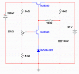
I am showing the positive regulator...the negative rail one is the same...inverted or mirrored..using PNP transistors....current inside the circuit is around 1 miliampere....only the rail pass transistor may face 30 miliamperes and the power on it will be the supply voltage, minus the adjusted voltage multiplied by the current.
In my case... 90 volts less 70 volts..this is equal 20 volts..... then multiplying by 0.030A...we have the series pass transistor dissipating.... 600 miliwatts.... 2 centimeter heatsink blade, aluminium blade..square..will be enougth..good idea to insulate the transistor from the heatsink, as you have 90 volts in the colector..so..have 90 volts at the heatsink.
regards,
Carlos
Using regulators and CCS you avoid this...or at least, the effects are greatly reduced.
Real thing is that supplies have voltage drop under consumption, at least DIY people supplies that are from Junk, from old dismounted amplifiers...when you buy a correct and honest one, then you do not need the stuff...plug 90 volts and be happy!
My supply, and several others, have 25% voltage drop when you drive hard the amplifier...so.... voltage reducing you gonna have this same voltage as the limiting factor to produce your output voltage swing.... mine, for instance, drop to 70 volts.... so... this will produce my output swing...70 positive and 70 negative.
While in stand by we gonna have 90 volts.... but the real thing will be 70.... this means you gonna avoid distortions, clipping if you reduce the input voltage to 70 volts..also you will not have some peaks....but they are distorted and are modulating things to your audio..dirty audio results from that.
Reason why the fokker will have a simple, 2 transistor each rail, "power rail power conditioner"...that will fix the maximum swing..voltage may variate in the output..but variations will be reduce to a very small percentual in the input circuitry..... you know.... translating to simple words..if driving hard the voltage will be 70.... why not to fix in 70 (my case)...... if we do different we gonna have distortion and peaks (this can be nice)..but distorted and modulated peaks, as supply goes dropping depending the power delivered to load and sucked from the supply.
There's a trimpot...then you can adjust to "your personnal case"..your reality..your supply hardly loaded...then knowing..you adjust the input voltage to this voltage..
I am showing the positive regulator...the negative rail one is the same...inverted or mirrored..using PNP transistors....current inside the circuit is around 1 miliampere....only the rail pass transistor may face 30 miliamperes and the power on it will be the supply voltage, minus the adjusted voltage multiplied by the current.
In my case... 90 volts less 70 volts..this is equal 20 volts..... then multiplying by 0.030A...we have the series pass transistor dissipating.... 600 miliwatts.... 2 centimeter heatsink blade, aluminium blade..square..will be enougth..good idea to insulate the transistor from the heatsink, as you have 90 volts in the colector..so..have 90 volts at the heatsink.
regards,
Carlos
Attachments
Now it is sounding high end.... another top performer....cannot beat Dx Blame ST, the
one, i think, is the best (at least i had not the chance to listen better ones).... but it is very close in performance.... huge power and high quality... ballanced sound.... not mids, nor highs and nor bass...it is playing ballanced now.... acoustically ballanced....not electrically ballanced (also it is flat).
Distortion dropped to 0.004%.... was a nice drop...i was having around 0.019%....phase is better.... waveform at 100 kilohertz reasonable.... speed (slew rate) seems good .... AC analisis flat to 4 Hertz... fourier with the harmonic distribution i like.
This is how it is today..... a big step forward done yesterday nigth.... now this is the second better amplifier i have built.
The voltage regulators you see in the left side..the input side, in the reality are special for me...because my supply has too much voltage drop...you may not need this...the place to this regulator to be is in the power supply board.
Do not assemble please..it is just a prototype.... i need time to check, to test more..to be sure about some details...this really needs 100 hours of observation of measurements, scope and listening.
The huge complication, in my point of view, usually does not sound fine...and i am in a struggle to increase sonics tweaking.... very small changes in part values and them the distortion increases.... really this kind of circuit needs tuning and will be hard to produce several units with the same characteristics or same performance because some capacitor and resistance and transistor choices are critical to reduce distortion.... a matter of fact, to me no doubts about...i knew that 20 years ago...the most complicated does not sound better than the simple ones..the over complicated "chups" (cannot use the real expression).... hard to make it so good as the generic Blameless, or my beloved super quality audio amplifier, the Dx Blame ST... at least, this monster gives you huge power...ballanced sound and also... the "psychological" satisfaction, as having voltage regulators, a lot of CCS, current sink, mirrors... a lot of parts (pure snake oil) will make the ones belief in such kind of stuff, feeling safe, as the circuit has some more modern features that should make it better than others... despite i do not think so.... i think people that has such kind of beliefs will feel good..will be sure has a better machine.
You see Nelson Pass...one of the best we have...skilled, a monster in know how... white hairs..expression of Albert Einstein in his eyes..... the example he give to us...simple...very simple.... and hot (aaaagh!)..... we go to the other side, complicating..because we are (ME!) very bad designers.... complicated folks..... some disturbed minds...if we are in France and we want to go to Rome...just take an airplane and go straigth to east or 10 degrees to southeast..... others, goes to Portugal, them go to Oslo, then go to Brussels, then pick another plane to Athens and then have an airplane to Rome.... this is the comparison.
regards,
Carlos
Attachments
Last edited:
- Status
- Not open for further replies.
- Home
- Amplifiers
- Solid State
- FOKKER, the competition nigthmare. name came from a Dutch man