Yes, you are right - they do listen in Japan as part of the design process.
You ar e using some very heavy transistors in your VAS Carlos -1302 and 3281. Are you sure this is a good idea?
Good luck with your amp.
You ar e using some very heavy transistors in your VAS Carlos -1302 and 3281. Are you sure this is a good idea?
Good luck with your amp.
Last edited:
No, i am not sure...it is a need only...i have not the driver ones
For sure, when released.... July, 17th, then i will suggest people to use drivers, and will suggest some models i have used and tried in the past.
I have tested power transistors in the place of real drivers and have not perceived difference..also in simulator nothing strange happens..also i have used power transistors as diodes, as heat sensor.
Well..amplifier is not aproved, not finished, just starting.... i have not even assembled.
I do have a precious pair here...one 2SC4793 and one 2SA1837...will try them as final test..and them will remove, as they are only for these cases...to enter the circuit to remove doubts, to compare sonically with the power ones..and then to return to my selection of good parts case, used to post testing prototypes.
I have to suggest these ones Bonsai...the real drivers, as people only believe if you have normal, traditional, schematic..if you do something strange..people very fast complain, or feel strange, or come to ask me things alike you did.
I do think they are better...and i do think this way because will have more acceptance by my customers, DIYers..forum builders... so..if they believe the most in these ones..i will offer what they want.... i need only to know what they think is the best driver..then i will suggest that one..as usually you replace them and nothing happens, exception is MJE15032 and MJE350 that use to oscilate very easy.
regards,
Carlos
This amplifier will be built soon..i am just waiting weather to give me a break
too much hot these last days.
having a break, in one day it will be ready.
regards,
Carlos
too much hot these last days.
having a break, in one day it will be ready.
regards,
Carlos
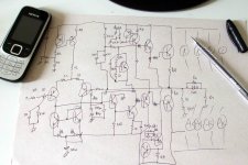
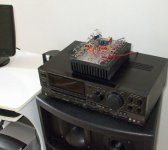
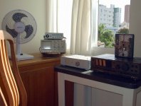
Structure, the skeleton for reference only
This is my guide..not to forget connections... watching this i will build.... after construction it is all fun to adjust, to tune, to measure and to inspect waveforms, to listen..it is fun and joy.
regards,
Carlos
This is my guide..not to forget connections... watching this i will build.... after construction it is all fun to adjust, to tune, to measure and to inspect waveforms, to listen..it is fun and joy.
regards,
Carlos
Attachments
Fokker supply is ready...plus and minus 90 volts
Of course the voltage will drop..but, simulating, i found that is possible to reach 52 volts rms at 2 ohms and 57 volts rms at 4 ohms... this means, depending how huge your supply, that you can reach 1.3Kw in 2 ohms and something near 800 watts rms at 4 ohms.
For these power, supply, to each channel must be 2Kw and 1.6Kw.... as you see...these are only numbers..reality is another thing.... real transformers, voltage dropping, them power is much less than that.
But, for sure, having good transformer, more than 400 watts is very easy, at 8 ohms.
Distortion remain very low, the worst case was 0.01%, and the best case was 0.0009% (THD)
Even having huge supply voltage drop....you may have very interesting short time peaks of power..and this adds a lot of realism to your sound reproduction.
Good one for powerholics...well...simulator thing for a while..we gonna see soon..the real world performance.
I think, using a good switching power supply, 2 ohms loads..then you can have 2.6 Kilowatts of power in your stereo.... important is a supply without voltage drop... amplifier power output depends supply voltage..if it is huge..then you may have huge power, in special when you reduce output load impedance.
regards,
Carlos
An externally hosted image should be here but it was not working when we last tested it.
Attachments
Last edited:
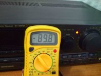
Fokker is working...testing using scope... will have fun doing that for several weeks
Also will listen music too, of course.
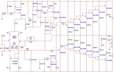
parts are the ones i have, this is the schematic today..tomorrow will be different...Vas is modified but can return the previous one...emitter resistances are the ones i have in big quantities..i think 0.22 ohms would be better..but i have not the ones..so..doing what i can with the parts i have.
Transistors are the ones i have...I do not like MJE340 and 15032....but had to use them..also i have not 2N5401 and 2N5551..only to the differential.
Real power measured was 255 watts rms - 7 ohms......because my supply has enormous voltage drop.... condensers for filtering are only 10 plus 10 thousand microfarads....much more than 400 watts rms is possible, over 7 ohms, IF the supply was huge.... to this supply, 4 output pairs would be reasonable.
Was not tested 4 ohms..because the limit will be the supply voltage/power.. and the one will drop even more if i plug lower impedance speakers...no increase of power possible, because the supply...so....i have not spent my time with that.
The CCS to the drivers now with increased current, 22 miliamperes was the last adjusted value.
This is the way it is now...latter may be different..for a while playing with it....i have promissed final schematic at July sevententh.
regards,
Carlos
Also will listen music too, of course.
parts are the ones i have, this is the schematic today..tomorrow will be different...Vas is modified but can return the previous one...emitter resistances are the ones i have in big quantities..i think 0.22 ohms would be better..but i have not the ones..so..doing what i can with the parts i have.
Transistors are the ones i have...I do not like MJE340 and 15032....but had to use them..also i have not 2N5401 and 2N5551..only to the differential.
Real power measured was 255 watts rms - 7 ohms......because my supply has enormous voltage drop.... condensers for filtering are only 10 plus 10 thousand microfarads....much more than 400 watts rms is possible, over 7 ohms, IF the supply was huge.... to this supply, 4 output pairs would be reasonable.
Was not tested 4 ohms..because the limit will be the supply voltage/power.. and the one will drop even more if i plug lower impedance speakers...no increase of power possible, because the supply...so....i have not spent my time with that.
The CCS to the drivers now with increased current, 22 miliamperes was the last adjusted value.
This is the way it is now...latter may be different..for a while playing with it....i have promissed final schematic at July sevententh.
regards,
Carlos
Attachments
Last edited:
Poor speakers.... will not be easy to find one that can hold all that punch
This is good for demolition, for building destruction.
Mein Got!
regards,
Carlos
This is good for demolition, for building destruction.
Mein Got!
regards,
Carlos
Bad designer uses to complicate things... flaws here and there, and more and more
subcircuits to fix all the mess...my amplifier is turning more and more crowdy...i had always that belief..that bad designers (me!) do this way...the good ones, alike Pass and others (Hugh Dean), do not overcomplicate things..they are good designers.
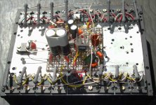
I have made modifications..and i am doing these things while building..real things....but ugly things, i am avoiding to show you too much.... my construction, the prototype is disgusting....looks very bad.
Why have i made modifications...why have i complicated?
The supply voltage drop...you see..wrong thing here and another there..and the mess is made....the hell supply has not power.... gives me 90 volts...but the amplifier while draining huge ammounts of current is reducing the voltage to 70 volts.....more than 20 percent..... what happens?
When the voltage is reduced to 70 volts... the signal entering, the volume entering the power amplifier, the audio amplitude, is good to drive the power amplifier to 400 watts....but the voltage dropping i have distortion, the amplifier cannot pump out more than 250 watts rms.... and this clips a lot.
Another problem was my beloved bootstrap..when supply voltage reduces, despite the stabilizing feature the bootstrap electrolitic condenser gives to us..i am having reduction of current to the VAS transistors, as they are feeded by current throught the bootstrapp (crosses the VBE limiter and then enters the VAS..the current does that).
This way, I HAD TO, include one more CCS (aaagh!) to turn that voltage drop less harming to the power amplifier...feeding VAS transistors using CCS (7mA more or less, the current).
Another problem was the way the amplifier was clipping...very ugly clipping when the voltage dropped...you imagine...first milisecond voltage is 90 volts..and them you have enormous peak power.... continuing with the imagination..something around 500 watts peak (not sure, not exactly).....but next milisecond, the supply voltage drops to 70 volts.....but the input level is big enougth to drive the amplifier to 500 watts..and now the power is 250 watts..what happens?..enormous ugly clipping...because of that i had to use the limiter...the small transistor i hate..the dinamic killer bandit!..but at least, it reduces the mess while this happens.... keep things under control..as the resistance to the negative (makes some grounding effect..the place where current is drained to) is reduced and overcurrent from the differential is drained..so..the enormous input signal is controled... as the current from the differential, the audio modulated current, is controled by a variating resistance
the small transistor has...from colector to emitter.
Sakis...you may be smilling...or laughing...... all rigth..this is you moment...you can say.
- " I told you uncle! "
This schematic is "today's schematic".... tomorrow, if needed, will be different.... more confused, more crowdy, alike all bad designer does (me!)
I have promissed to release July the sevententh..so..i have time.... a gift, from me to myself...my birthday...i hope with my bariatric operation already aproved when this time arrives.
regards,
Carlos
subcircuits to fix all the mess...my amplifier is turning more and more crowdy...i had always that belief..that bad designers (me!) do this way...the good ones, alike Pass and others (Hugh Dean), do not overcomplicate things..they are good designers.
I have made modifications..and i am doing these things while building..real things....but ugly things, i am avoiding to show you too much.... my construction, the prototype is disgusting....looks very bad.
Why have i made modifications...why have i complicated?
The supply voltage drop...you see..wrong thing here and another there..and the mess is made....the hell supply has not power.... gives me 90 volts...but the amplifier while draining huge ammounts of current is reducing the voltage to 70 volts.....more than 20 percent..... what happens?
When the voltage is reduced to 70 volts... the signal entering, the volume entering the power amplifier, the audio amplitude, is good to drive the power amplifier to 400 watts....but the voltage dropping i have distortion, the amplifier cannot pump out more than 250 watts rms.... and this clips a lot.
Another problem was my beloved bootstrap..when supply voltage reduces, despite the stabilizing feature the bootstrap electrolitic condenser gives to us..i am having reduction of current to the VAS transistors, as they are feeded by current throught the bootstrapp (crosses the VBE limiter and then enters the VAS..the current does that).
This way, I HAD TO, include one more CCS (aaagh!) to turn that voltage drop less harming to the power amplifier...feeding VAS transistors using CCS (7mA more or less, the current).
Another problem was the way the amplifier was clipping...very ugly clipping when the voltage dropped...you imagine...first milisecond voltage is 90 volts..and them you have enormous peak power.... continuing with the imagination..something around 500 watts peak (not sure, not exactly).....but next milisecond, the supply voltage drops to 70 volts.....but the input level is big enougth to drive the amplifier to 500 watts..and now the power is 250 watts..what happens?..enormous ugly clipping...because of that i had to use the limiter...the small transistor i hate..the dinamic killer bandit!..but at least, it reduces the mess while this happens.... keep things under control..as the resistance to the negative (makes some grounding effect..the place where current is drained to) is reduced and overcurrent from the differential is drained..so..the enormous input signal is controled... as the current from the differential, the audio modulated current, is controled by a variating resistance
the small transistor has...from colector to emitter.
Sakis...you may be smilling...or laughing...... all rigth..this is you moment...you can say.
- " I told you uncle! "
This schematic is "today's schematic".... tomorrow, if needed, will be different.... more confused, more crowdy, alike all bad designer does (me!)
I have promissed to release July the sevententh..so..i have time.... a gift, from me to myself...my birthday...i hope with my bariatric operation already aproved when this time arrives.
regards,
Carlos
Attachments
This way, I HAD TO, include one more CCS (aaagh!) to turn that voltage drop less harming to the power amplifier...feeding VAS transistors using CCS (7mA more or less, the current).
Carlos
Finaly !! you won t regret it...
Attachments
Last edited:
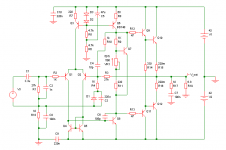
I have compared two types of VAS...one using two transistors and other a simple one
I am keeping the CCS to feed VAS, but i am using the simple VAS..a single transistor, because sounded better to me.
Here the schematic... also made , assembled and tested this morning.
regards,
Carlos
I am keeping the CCS to feed VAS, but i am using the simple VAS..a single transistor, because sounded better to me.
Here the schematic... also made , assembled and tested this morning.
regards,
Carlos
Attachments
This one is the version 1.4, the one i like the most, compared to the previous ones
All them assembled, observed using scope and played music too.
This is not the final one..it is just the last version i have build..there are many things i will change
There are missing parts and transistors to be substituted.
regards,
Carlos
All them assembled, observed using scope and played music too.
This is not the final one..it is just the last version i have build..there are many things i will change
There are missing parts and transistors to be substituted.
regards,
Carlos
Attachments
Last edited:
Because listening tests, also because simulator results
having better square wave in 20 Kilohertz (almost perfect) and lower THD distortion, then i decide to use this feedback arrangement in the Fokker amplifier.
Attached the last schematic and my source of inspiration. (copy!)
The pdf attached is the Fokker, version 1.5 .... it was tested and simulated...it is playing here at my home.
regards,
Carlos
Attachments
It is really overcomplicated.
Do not be alarmed, the Fokker is really overcomplicated, it seems crowdy ...produces some fear on us.... excesses in circuits quantity, these peripherals help somewhat, but usually does not work very good .... amplifiers very crowdy this way, with exceptions of course, sounds very bad,especially when their complications (features) are inside the audio patch .... Fokker has a lot of surrounding sub circuits, auxiliary Constant Current Sources (CCS) ... you see that removing all these auxiliary circuits, it will look not too much different than a very simple and quite generic amplifier ... these subcircuits, auxiliary CCS, are creating to me a lot of problems.. it is hard to reduce harmonic distortion, and to make better the harmonic distribution... The sound is excellent..but, does not measure as well as the Dx Blame ST for example.
regards,
Carlos
Attachments
Last edited:
I am researching ... studying, watching effects, changing parts, reading books
Search for ideas in other schematics we find in the WEB, also professional schematics.
Today i gave a good step up doing some modifications in compensation..also output filter.
You have the insertion of a capacitor (1uF) in parallel with the load...now it is better...but i want to insert 2.2uf and full power square wave.... this is one of the goals to achieve.... to try at least...if i fail to do that..then you gonna know..i will let you know the weeknesses.
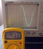
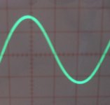
Some waveforms... 10 hertz full power (sinus).... 35 hertz full power (sinus).. 20 kilohertz full power square wave.... the amplifier is reproducing a clean sinusoidal waveform at 100 Kilohertz... and can put out half power at 1 Hertz.
Not only waveforms but also simulator results and sonics are very good (not better than Dx Blame ST)... but very powerfull....it can put out 52 volts RMS... the maximum i could installing DC supplies in parallel was to achive 47 Volts.
Notice that 52 volts is easy and possible, depending your transformer...and simulator confirmed it can put out more than 1100 watts RMS in 2 ohms..this is for powerholics
Here a fast video about the fokker:
YouTube - Output capacitor to ground - Fokker.avi
regards,
Carlos
Search for ideas in other schematics we find in the WEB, also professional schematics.
Today i gave a good step up doing some modifications in compensation..also output filter.
You have the insertion of a capacitor (1uF) in parallel with the load...now it is better...but i want to insert 2.2uf and full power square wave.... this is one of the goals to achieve.... to try at least...if i fail to do that..then you gonna know..i will let you know the weeknesses.
Some waveforms... 10 hertz full power (sinus).... 35 hertz full power (sinus).. 20 kilohertz full power square wave.... the amplifier is reproducing a clean sinusoidal waveform at 100 Kilohertz... and can put out half power at 1 Hertz.
Not only waveforms but also simulator results and sonics are very good (not better than Dx Blame ST)... but very powerfull....it can put out 52 volts RMS... the maximum i could installing DC supplies in parallel was to achive 47 Volts.
Notice that 52 volts is easy and possible, depending your transformer...and simulator confirmed it can put out more than 1100 watts RMS in 2 ohms..this is for powerholics
Here a fast video about the fokker:
YouTube - Output capacitor to ground - Fokker.avi
regards,
Carlos
An externally hosted image should be here but it was not working when we last tested it.
Attachments

Last edited:
I have tried this fokker amplifier using CCS to feed the voltage amplifier stage
and also have tried a bootstrap...of course, both with almost the same current (2 percent difference maximum).
I realise, listening, the bootstrap sounds better...but CCS measure a little bit better.... waveforms are a little bit better.
regards,
Carlos
and also have tried a bootstrap...of course, both with almost the same current (2 percent difference maximum).
I realise, listening, the bootstrap sounds better...but CCS measure a little bit better.... waveforms are a little bit better.
regards,
Carlos
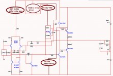
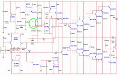
Fokker feature will be a switch, a CCS-Bootstrap switch
This way people will be able to find out the one is better for his ears.
Dx produces the best for you.... all i want is to see you happy....i can explain you how this works in details if needed..just let me know by direct mail... your name will be classified, your message will be confidential.
Switch inside green circle.
The amplifier is in development.
regards,
Carlos
Attachments
Carlos, I know you use what you have on hand, heatsinks etc
But really think you should think a bit further ahead, and plan the complete build with a more practical layout....like say, thinking about common available box size, boards with short logical wire connections, etc
Instructions for hardwired output devices would be good too, as its a really simple thing a lot of people should learn
Another small matter
It seems to me that from a space saving point, placing some of the resistors in "upright" position might make sense
Attachments

- Status
- Not open for further replies.
- Home
- Amplifiers
- Solid State
- FOKKER, the competition nigthmare. name came from a Dutch man