Salas, here you go, the first LC filter I showed, with 25pF parasitic capacitance on L. Finesse has no parasitics added.
Still I'm asking, if the finesse reg was perfect, would it be worth building only for the past 10MHz better psrr? Also, what do the RF guys use to clean up HF garbage? Ferrite?
Still I'm asking, if the finesse reg was perfect, would it be worth building only for the past 10MHz better psrr? Also, what do the RF guys use to clean up HF garbage? Ferrite?
Attachments
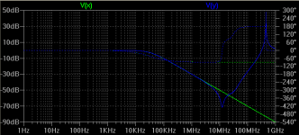
There must be some parasitic R too?
Don't know, seems too much for audio looking in tens of MHz. I don't think that a practical layout would achieve easily anyway.
Don't know, seems too much for audio looking in tens of MHz. I don't think that a practical layout would achieve easily anyway.
Salas, here you go, the first LC filter I showed, with 25pF parasitic capacitance on L. Finesse has no parasitics added.
Still I'm asking, if the finesse reg was perfect, would it be worth building only for the past 10MHz better psrr?
Wenzel does among the best high precision oscillators, which usually work in the 2-50 mhz region.
Also, what do the RF guys use to clean up HF garbage? Ferrite?
Well tuned ferrite works (anyway this is my opinion), but they enclose the clocks in metal boxes. For ferrites, we can google RF stuff for radio-amateurs, there's quite some literature 🙂
There must be some parasitic R too?
Yes, parasitic R included.
Telstar said:Wenzel does among the best high precision oscillators, which usually work in the 2-50 mhz region.
They certainly seem to know what they're doing. But maybe a simple passive low pass filter can get the work done.
Sure, I don't expect a regulator to do anything at 1MHz even, let alone 10MHz. But the finesse regulator is really a filter, OK. In the end, who cares what it's called. But my point is the following: why bother building the finesse thing if you can get similar results with a simple inductor, resistor, and capacitor passive filter?
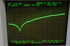
Good, so have a look at the second image I attached: a L-C||R filter. The toroid inductor I pulled out of a computer power supply. It measures at 15.9mH with a Q of about 18. The two caps are about 30nF, in parallel with 200R resistor. The C || R are from signal to ground, after the L. Plugged this into the spectrum analyzer and see what it does up to 40MHz?
The dip is at about 8MHz, approximately -78dBm. The marker, right in the center, about 20MHz, -40.2dBm. I'm sure that inductor has high capacitance, and this is what how it filters HF junk.
Out of curiosity I might build the finesse filter and see what it does.
Attachments
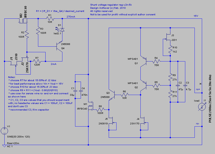
I just got an idea for a potential improvement. Replace R1 in rev 5k with a home made inductor, made from nichrome wire. This is the wire used in hairdryers for instance. Has high resistivity per foot and can take a lot of heat. Its resistance increases lightly with heat, so this one has to be tested. What I have in mind is to take a piece of nichrome wire measured for approximately 10 ohms, and then wind it on a ferrite toroid to obtain an inductor. Of course the toroid has to be painted over so that its surface is not conductive. Depending on the ferrite material, you can get an inductor from a few uH up to even 3-4 mH.
Of course, if you have the patience to wind a long copper wire onto a core you will get the same resistance but MUCH higher inductance. Of course you will have to use the correct diameter wire for the current that you want the regulator to work at.
What's the improvement? Higher ripple rejection!
Here's the schematic again to illustrate where R1 is.
@Iko
Looks you are on the right road, Erno use inductors in his high performance PS for regs.
Looks you are on the right road, Erno use inductors in his high performance PS for regs.
Good point. Well, it was just a crazy idea that came to me out of the blue; haven't thought this one out. I'll see if I can come up with anything like this that would promise a practical improvement.
Edit: here's a nice little experiment someone carried on the DC effect on cored inductors and how to deal with it.
http://www.cliftonlaboratories.com/dc_transformer_saturation.htm
An alternative would also be chokes which are intended for filtering, with the proper DC resistance and DC current rating. Probably not worth it though.
Last edited:
Is it possible that an inductor at R1 would also improve output impedance? I wonder is the affect is significant.
- keantoken
- keantoken
not crazy idea, but better to use inductor between rectifier and regulator, like C-L-C
Sure, as a pre-filter I'm fond of LC already 🙂
Have not, but I happen to have one in my office at work. If I get some time tomorrow will post some results. Do you have any experience with it?
I have a few RF chokes up to 470uH sitting on the shelf that can be used.
But your regulator has already some 160dB plus ripple rejection, why bother?
My LCLC raw supply would have got rid of all high frequency junks.
But your regulator has already some 160dB plus ripple rejection, why bother?
My LCLC raw supply would have got rid of all high frequency junks.
@iko
only multimeter experience with those chokes 🙂
Measured some of them, 0.3 - 1.5 H, depends on type.
only multimeter experience with those chokes 🙂
Measured some of them, 0.3 - 1.5 H, depends on type.
OK, something for your thought.
It sometimes works well with opamp that you bypass with a 0.1uF or 0.01uF capacitor from the positive rail to negative rail, i.e. rail to rail, not rail to ground.
I tried that today. The regulator oscillated wildly.
Thoughts?
It sometimes works well with opamp that you bypass with a 0.1uF or 0.01uF capacitor from the positive rail to negative rail, i.e. rail to rail, not rail to ground.
I tried that today. The regulator oscillated wildly.
Thoughts?
- Status
- Not open for further replies.
- Home
- Amplifiers
- Power Supplies
- My take on a discrete shunt voltage regulator