Check if DC voltages on both boards are the same, you should have clean sinewave at base and collector of Q8 (VAS). Check the termistor T2, AC signal at D+, D-. Please post all the measured voltages so it will be easier for people to help you. The C8, C9 68pF at the drivers compensate for signals above 1MHz.
Check if DC voltages on both boards are the same, you should have clean sinewave at base and collector of Q8 (VAS). Check the termistor T2, AC signal at D+, D-. Please post all the measured voltages so it will be easier for people to help you.
Thanks for your advice. Can you clarify a couple of things for me (I am the rankest of beginners)?
By "check DC Voltages are the same" are you referring to PS voltages? Those have been checked and are fine. Or do you mean something else?
What does VAS mean?
How do I check a thermistor? For resistance?
I will check Q9 and Q10 and measure VAC at D+ and D-. I will also post waveforms taken at the B and C of Q8. Of course I will post all the data I collect.
I thought I should also check C5 since it is an electrolytic and in the bias circuit. I'll check P1 as well.
Many thanks again.
cheers,
Fred
Fred, if you want to send me transistors to run on the curve tracer, I'd be happy to do that and post/send you the photos when I return the transistors. Price is free as I'm curious as to what is going stupid on you.
Thanks G2. Very kind. I'll definitely send you the transistors I pull. PM me your address. But if I can, shouldn't I just replace the parts with new, tested parts?
Do you agree that Q9 and Q10 are likely suspects?
thanks yet again,
Fred
I disagree as I have one that behaves properly AND the other channel of Fred's unit works correctly as well. Rather than trying to improve on Nelson Pass's work, we should find out what it wrong with it.
Fred, if you want to send me transistors to run on the curve tracer, I'd be happy to do that and post/send you the photos when I return the transistors. Price is free as I'm curious as to what is going stupid on you.
G²
Without this compensation, the amps are doomed to oscillate
wether instantly or in presence of a signal.
This is not an improvement, as it s a basic principle to
be respected in any amp.
Any beginner in design is aware about this.
Without this compensation, the amps are doomed to oscillate
wether instantly or in presence of a signal.
This is not an improvement, as it s a basic principle to
be respected in any amp.
Any beginner in design is aware about this.
With all due respect, this is not the thread to debate to merits of this amplifier design. I am simply seeking to repair a component that has given more than two decades of reliable operation.
I invite you to start another thread discussing how this design may, or may not, be improved. I would follow such a thread with great interest.
regards,
Fred
You are not the only one by there, and what i did write is not
off topic.
Other people might be less stubborn and understand that the source
of their problem might be an amp oscillating, and thus displaying
what appears as hasardous bias points.
So i invite you as well to not take the other s people feelings
as automaticaly in phase with yours..
You are free to ignore my saying,but please, just don t tell me
what i have to do or not to do.
Without this compensation, the amps are doomed to oscillate
wether instantly or in presence of a signal.
This is not an improvement, as it s a basic principle to
be respected in any amp.
Any beginner in design is aware about this.
Nelson Pass is not a beginner and the amps by and large work - just this one channel. Why does mine work? Why does one channel of Fred's work? I would think that would be far more interesting than altering the design of the unit because 'any beginner in design is aware of this'. I'm sorry, I really want to know why, not what beginners think.
G²
I didn t know that Nelson Pass was the designer of this beast...
He s often by there, so you can ask him what it is all about, i m sure
he will give an helpful hand.
Now, about your question, this has surely to do with the fact that
your speakers are not very reactive loads; thus, the amp can be stable
with some luck.
Be aware that stability whith no signal doesn t prevent
the amp oscillations occuring as soon as a signal is fed.
Often, this translate to devices heating more than expected.
Anyway, good luck with your investigations..
I did look at the scheamatic again, and indeed, the amp is compensated.
C2 (20pF) provide the compensation.
It s just that the value is very optimistic.
In a differential amp like this one, the good value lays between 47 and 100pF.
C2 (20pF) provide the compensation.
It s just that the value is very optimistic.
In a differential amp like this one, the good value lays between 47 and 100pF.
Finally got some more work done on this.
1. Removed and tested Q9 and Q10. They both passed the diode test with my DVM and the IT-18 leakage test. Their gain was borderline (203, 179hfe) so I replaced them both with tested 2240 and 970 transistors with in-spec gains (390, 379hfe).
2. Tested R21, it was dead on. Replaced it with a tested new resistor since it was unsoldered.
3. Removed and tested C5, it was correct at 4.84uf. Replaced it with a fresh new 'lytic (tested at 5.01uf).
4. With no load on the amp, I put 1.0vac, 60hz sinewave in at the RCA input. With power at 30% (approx. 36vac), I measured VDC and VAC at D+ and D- on both channels:
Good Channel: D+ 0vac, +1.0vdc, D- 0vac, -1.0vdc
Bad Channel: D+ 20.6 vac, +3.8vdc, D- 20.3 vac, +1.9 vdc
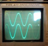
5. With the same input, I raised the power to 50%. I obtained the attached traces. The upper trace (ch1) is the input signal, the lower trace is output at the speaker outs. You can plainly see it is still oscillating.
So I guess the next question is, why do I have positive VDC at D- and VAC at D+ and D- on the bad channel?
1. Removed and tested Q9 and Q10. They both passed the diode test with my DVM and the IT-18 leakage test. Their gain was borderline (203, 179hfe) so I replaced them both with tested 2240 and 970 transistors with in-spec gains (390, 379hfe).
2. Tested R21, it was dead on. Replaced it with a tested new resistor since it was unsoldered.
3. Removed and tested C5, it was correct at 4.84uf. Replaced it with a fresh new 'lytic (tested at 5.01uf).
4. With no load on the amp, I put 1.0vac, 60hz sinewave in at the RCA input. With power at 30% (approx. 36vac), I measured VDC and VAC at D+ and D- on both channels:
Good Channel: D+ 0vac, +1.0vdc, D- 0vac, -1.0vdc
Bad Channel: D+ 20.6 vac, +3.8vdc, D- 20.3 vac, +1.9 vdc
5. With the same input, I raised the power to 50%. I obtained the attached traces. The upper trace (ch1) is the input signal, the lower trace is output at the speaker outs. You can plainly see it is still oscillating.
So I guess the next question is, why do I have positive VDC at D- and VAC at D+ and D- on the bad channel?
Attachments
Last edited:
I have two of these amps also and have never had a problem.
Considering that we know the design is solid, the most likely reason is that replacement semis you substituted have different ft or capacitance characteristics. Another possibility is that you did not find all the failed parts. Can you please list which semis you have replaced and what substitutions you made. Let's assume for now that any other parts you replaced could not have caused the problem.
You have positive voltage at D- because there is pos DC offset at the output.
A quick thought would be to increase C2 to 100 or 200 pF just while you are testing the output stage. First see if the oscillation goes away, if it does then it is a global loop problem probably caused by the substituted parts, if not then there might be a local oscillation somewhere. If the oscillation stops, you should be able to see low DC offset, set a stable Bias point, and see good behavior at full voltage and full power output. Otherwise you might not have found all the failed components.
Last edited:
Can you please list which semis you have replaced and what substitutions you made. Let's assume for now that any other parts you replaced could not have caused the problem.
Thanks for the reply, Pete. The following semis were replaced. No substitutions were made.
Q4 (2sc2912)
Q7 (2sa1210)
Q8 (2sa970)
Q9 (2sa970)
Q10 (2sc2240)
All of these were checked for leakage and gain prior to installation. Q4 and Q7 are matched, as are Q9 and Q10.
The only truly "bad" part I have identified was Q7 (B-E short).
A quick thought would be to increase C2 to 100 or 200 pF just while you are testing the output stage. First see if the oscillation goes away, if it does then it is a global loop problem probably caused by the substituted parts, if not then there might be a local oscillation somewhere. If the oscillation stops, you should be able to see low DC offset, set a stable Bias point, and see good behavior at full voltage and full power output. Otherwise you might not have found all the failed components.
I have a 300pf mica cap, would that work for the experiment? I also have a direct replacement for C2 I could install.
A quick thought would be to increase C2 to 100 or 200 pF just while you are testing the output stage. .
Lol...
I already proposed to check the compensation, but the guy
is stubborn..
"It was designed by Nelson Pass" was the answer..😀😀
Useless to change transisors that goes blown each time due to
oscillation...😀
Lol...
I already proposed to check the compensation, but the guy
is stubborn..
"It was designed by Nelson Pass" was the answer..😀😀
Useless to change transisors that goes blown each time due to
oscillation...😀
There's really no need for the mocking tone. I freely admit I am new and learning. Perhaps there is a language barrier, but I read your previous posts as questioning the design, not suggesting a path for troubleshooting. Since my experience with this amp has been over 20 years of reliable service (indeed, as Pete's experience is with two of these amps), I could see no logical reason to question the design at this point, regardless of who created the design. If it worked for 20+ years, the design works!
I can see the value of checking the compensating caps, and I appreciate you pointing that out. I'm pursuing that strategy now.
FWIW, I have not blown a single replacement component since I am keeping operating voltage to a minimum and not running loads.
FWIW, I have not blown a single replacement component since I am keeping operating voltage to a minimum and not running loads.
Good..No casualty, that s the essential..
Anyway, good luck, we all have messed with reluctant amps.
Quite not a cakewalk..
Lol...
I already proposed to check the compensation, but the guy
is stubborn..
"It was designed by Nelson Pass" was the answer..😀😀
Useless to change transisors that goes blown each time due to
oscillation...😀
Since thousands of these work as advertised without oscillating, I truly don't see how altering the circuit to get rid of oscillations is anything but a Band-Aid repair. The problem isn't solved, just one of the symptoms - or is that a temporary alteration to pin down the REAL problem? I'm also concerned as to why the top of the signal is clipping before the oscillations start with no clipping on the negative portion. BTW, at that Variac voltage setting, does the other channel show any clipping and if so, is IT symmetrical and is the gain different/the same? It keeps pointing back to the long-tailed pair Q1 and Q2. I think you'll find a rather large imbalance in the currents between Q1 and Q2. Fred also mentioned earlier that the gain is different between the channels and unless resistors are off-value, it ALSO points to the input as that is where the feedback takes place. I don't think the outputs and drivers have problems but I'd certainly like to see the results on a curve tracer of ALL the semiconductors. SOMETHING is rotten here.
I suspect one of the transistors will show the equivalent of a resistor in parallel with one of the junctions. I only ran across one like that in '75 or '76 but it had a LOT of peculair symptoms including asymmetrical clipping though I don't remember if there were oscillations.
BTW, Nelson Pass DID design it.
G²
Ok I have some catching up to do here, so if you made no substitutions then it really should be stable. It might be that some of the new transistors are fakes, probably not, or that they are improved with a higher ft again probably not.
I want to back up a bit, why would the VAS transistor fail, it even has a protection transistor on it Q8? It is possible that it is just ageing or a line transient I suppose. I would be suspicious of all the transistors around it, just in case something really went wrong. I know you've done a lot of testing I have to go back and read more I'm on page 3 right now.
Also, if Q7 went open on the collector, the output should have gone to -80V not +80. did you note the polarity? If C to E shorted then yes it would have gone to +80.
I'll skim more to try to catch up. I would hold off on the cap until we look into a few more things. It would be good to get the EBC voltage on all the transistors with no signal and a multimeter referenced to ground.
Another consideration is that I'm not certain that the design is stable at a really low voltage like +/- 10 or 20 on the rails. You might need to get to 40 or more at least. You could add the series light bulb that people have talked about if you want to try more voltage, and/or you could change the output stage fuses to 1A and not run it into a load. These precautions should save your outputs if something is still wrong.
I think the amp might be working and is just not stable at the low voltage, but you seem to have DC offset also.
About changing parts, I would certainly replace the electrolytic caps C5 and C3 just to rule them out. They are just too old to trust.
I checked the schematic...
is the high dc voltage stll here after all the trannies changes you made?
is the high dc voltage stll here after all the trannies changes you made?
I want to back up a bit, why would the VAS transistor fail, it even has a protection transistor on it Q8? It is possible that it is just ageing or a line transient I suppose. I would be suspicious of all the transistors around it, just in case something really went wrong. I know you've done a lot of testing I have to go back and read more I'm on page 3 right now.
Q8 was replaced, but it did not test open or shorted.
Also, if Q7 went open on the collector, the output should have gone to -80V not +80. did you note the polarity? If C to E shorted then yes it would have gone to +80.
Q7 was shorted across B-E. I'm afraid I did not note the polarity and could easily have missed that data so early in the process. Doh.
I'll skim more to try to catch up. I would hold off on the cap until we look into a few more things. It would be good to get the EBC voltage on all the transistors with no signal and a multimeter referenced to ground.
Another consideration is that I'm not certain that the design is stable at a really low voltage like +/- 10 or 20 on the rails. You might need to get to 40 or more at least. You could add the series light bulb that people have talked about if you want to try more voltage, and/or you could change the output stage fuses to 1A and not run it into a load. These precautions should save your outputs if something is still wrong.
I think the amp might be working and is just not stable at the low voltage, but you seem to have DC offset also.
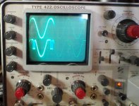
I think the design becomes stable at about 60% of operating voltage (72 vac or so) This is about 40vdc on the rails. You can see it on the scope. The first shot shows the good channel input (top) and output traces. I can watch the output trace go from clipped to correct as I turn up the variac. The second shot shows the bad channel in and out traces at the same operating voltage. So, no sadly, I don't think the amp is working.
Great idea on the fuses. I put in some 2amp as that's all I had. I'm not running any loads for tests.
So this brings up a question, to measure the EBC voltages do I need to be at that high of an operating voltage? Or can I run it lower? I could compare values to the good channel and look for differences.
About changing parts, I would certainly replace the electrolytic caps C5 and C3 just to rule them out. They are just too old to trust.
I replaced C5, but for C3 I only have a 47uf 100v (not 10v as installed now). That shouldn't make a difference, right? (It's worth noting that in the next rev of this board, Adcom went to a 100v cap for C3.)
Attachments

- Home
- Amplifiers
- Solid State
- Another high DC Adcom GFA-555