I think the "take no prisoners" manner of posting is not helpful when it's extended to imputation of personal motive.
Certainly not true to think Geddes was promoting sale of his subs in his intervention here. He's been pretty clear here and elsewhere that the bass management ideas he's been promoting can be accomplished with any sort of competently designed subs.
He certainly did not mention here his own subs.
So what's up? There was the potential for perhaps some interesting discussion almost certainly cancelled by intemperate speech.
How will this work, if at all 😕
Model it in Akabak and see.
If you provide detailed dimensions and driver T-S specs I'll do it.
I think the "take no prisoners" manner of posting is not helpful when it's extended to imputation of personal motive.
Certainly not true to think Geddes was promoting sale of his subs in his intervention here. He's been pretty clear here and elsewhere that the bass management ideas he's been promoting can be accomplished with any sort of competently designed subs.
He certainly did not mention here his own subs.
So what's up? There was the potential for perhaps some interesting discussion almost certainly cancelled by intemperate speech.
I'd like to see this get back on track however I'm not going to just go silent when I see absurd statements being made.
Geddes admits in post # 548 that he is not a TL expert, even suggests that he should stay out of the discussion:
http://www.diyaudio.com/forums/multi-way/161961-real-expert-just-self-proclaimed-55.html#post2112217
Then claims in post #555: "Even at the first resonance of the TL these electrical circuits analogs are no longer valid. " With a further suggestion that lumped models and therefore T&S theory were not useful.
This is entirely false by the way and it is in response to my post #550 where I stated that the electrical model was an accurate analogy. My paper otherwise would not have been accepted by a real expert in the field at a top notch school.
Several here have tried to dismiss the electrical analogy in an attempt to discredit my work. Self proclaimed experts it would seem.
I find this foolish talk annoying and irritating, such completely false statements are probably deliberate with the intent to make the real expert go away. I did the work, wrote the paper, and had it reviewed with more scrutiny than my Master's thesis. No I don't need the approval of Internet "experts."
Listen, I've been on the net for far more than 10 years, seen all the pathetic ways of trying to twist a discussion, and I'm not going to waste my time.
It is clear to me that Geddes was promoting both himself and his sub products, with absurd claims.
Last edited:
If you provide detailed dimensions and driver T-S specs I'll do it.

Let me ask you, does the box you are showing have any port going outside the box? It doesn't look like it, just asking.
Let me ask you, does the box you are showing have any port going outside the box?
I expected it would look strange
No, completely closed
Closed mass loaded pseudo TL🙄
I will see if I can spot a good woofer
Which direction to take it depends on whether it works and how
If at best, low bass with low Qts driver, and still being a closed system
Attachments
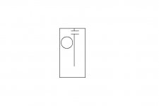
..I expected it would look strange
..Closed mass loaded pseudo TL🙄
Hi tinitus,
Pseudo loaded?🙂
 :the wave bouncing back and forth in the box is illustrated here:🙄
 b
Attachments
Several here have tried to dismiss the electrical analogy in an attempt to discredit my work.
I for one haven't seen your work, so i can't judge (i'd love to see it).
Augspurger uses an electrical analogy based on transmission lines (unfortunately a 1 hit wonder so only informational now), and Martin uses a 1D mechanical analog. He has refined the model for >10 years, vetted it with 3D FEM, and has a decade of real world feedback.
When they both came out, both produced the same results, which i take as a validation of both. Martin's has since become more detailed and accurate. Martin's charts go up to 1k, he advises that accuracy starts dropping above 400 Hz. Augspurger's breaks down earlier.
Since we are trying to model bass that is good enuff.
dave
Just to move this along:
Vifa P17 Mass Loaded Quarter Wave designs
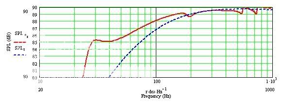
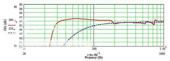
The above simulations use the same parameters for a subject driver. The top sim is intended to make use of room gain to arrive at a "flat" response in room. In my experience this response is less subject to "boom" due to room modes. YMMV
The bottom sim is an exercise in attaining a "flat" response from the baffle. The area under the red curve, above the blue dash line, is the gain of the system from the terminus.
Vifa P17 Mass Loaded Quarter Wave designs
The above simulations use the same parameters for a subject driver. The top sim is intended to make use of room gain to arrive at a "flat" response in room. In my experience this response is less subject to "boom" due to room modes. YMMV
The bottom sim is an exercise in attaining a "flat" response from the baffle. The area under the red curve, above the blue dash line, is the gain of the system from the terminus.
.
Geddes admits in post # 548 that he is not a TL expert, even suggests that he should stay out of the discussion:
http://www.diyaudio.com/forums/multi-way/161961-real-expert-just-self-proclaimed-55.html#post2112217
Then claims in post #555: "Even at the first resonance of the TL these electrical circuits analogs are no longer valid. " With a further suggestion that lumped models and therefore T&S theory were not useful.
This is entirely false by the way and it is in response to my post #550 where I stated that the electrical model was an accurate analogy. My paper otherwise would not have been accepted by a real expert in the field at a top notch school.
My assumption, and I expect that of most readers here, is that both you and Geddes are experts with regard to speaker design.
It seems to me you both have a great deal to say that's of interest.
It could be wise sometimes to give folk, especially bright ones, a little slack in case what they're doing is thinking out loud, so to speak, and the ideas may not be completely formed. This is surely a good idea when someone like Geddes makes, what at the surface, appears to be an extraordinary claim.
A ferocious response is not likely to lead in a productive direction.
'Making the expert go away.' Well, you and Geddes have at least one thing in common.Several here have tried to dismiss the electrical analogy in an attempt to discredit my work. Self proclaimed experts it would seem.
I find this foolish talk annoying and irritating, such completely false statements are probably deliberate with the intent to make the real expert go away.
Quoting the paragraph of his you refer to at the top here:I did the work, wrote the paper, and had it reviewed with more scrutiny than my Master's thesis. No I don't need the approval of Internet "experts."
Listen, I've been on the net for far more than 10 years, seen all the pathetic ways of trying to twist a discussion, and I'm not going to waste my time.
It is clear to me that Geddes was promoting both himself and his sub products, with absurd claims.
That is hardly "promoting...his sub products" is it? I think you are pulling the trigger far too quickly.I should probably stay out of this discussion since I am not an expert on TL designs and what works and what doesn't. I long ago stopped caring much about specific LF tunings and designs since I see the solution to LFs in room to be the use of multiple sources and "bass managment" - how the individual sources are designed is a distant secondary concern IMO. To me, they will most likely all work the same once properly setup. Yesterday 05:27 PM
The above sim's demonstrate the ability to design a Quarter Wave cabinet and tailor the response to complement a specific room gain. Earlier, I cited a response of +/- 1.5 dB...I think I sandbagged a little...😉
OK Ed, how about telling us more about the designs that produced those two very different SPL curves using the same driver. I have to admit I have not seen anything like that before and would be interested in more details.
Hi:
I'm newly logged in here and have been lurking this thread for a couple of days.
In post 563 'PB2' wrote:
Several here have tried to dismiss the electrical analogy in an attempt to discredit my work. Self proclaimed experts it would seem.
I find this foolish talk annoying and irritating, such completely false statements are probably deliberate with the intent to make the real expert go away. I did the work, wrote the paper, and had it reviewed with more scrutiny than my Master's thesis. No I don't need the approval of Internet "experts."
and while I don't know of the paper you refer to I wonder if I might be able to see copy of it.
Thanks,
Bill Perkins - PEARL
Last edited:
OK, I'll try...You really need to be more specific here.
Agreed. So for a transmission line speaker, where the dimensions of the acoustical elements are large, the lumped model is only valid and accurate at very low frequencies (below the first resonance, in fact).The lumped model is valid and accurate for all frequencies where the wavelengths are long compared to the dimensions of the acoustical elements.
Agreed. Unfortunately, reflections and resonances in a line can't be properly modeled with lumped impedance models.Now, a TL speaker is a completely different animal, the far end is not match terminated and therefore there are reflections and resonance on the line.
Agreed. The fact that a transmission line is not a lumped parameter system suggests that a lumped parameter model may not be appropriate.What makes a transmission line is the fact that it is not a lumped parameter system, there are both capacitance and inductance distributed down the line and partial differential equations are required to model such a system.
I can't self-quote as my earlier post was deleted, but I think Earl summed it up quite nicely here:
Or, as you put it:Lets please remember that these "circuit" type analogies are limited to LFs. Even at the first resonance of the TL these electrical circuits analogs are no longer valid.
Also, consider the intent for these lumped models, which was to model very low frequencies!
<snip>
Know your tools, understand their limitations.
Transmission line speakers can be accurately modeled, but not with lumped parameter models. Approaches such as that used by Martin King are much more appropriate.
p.s. Please don't take any of the above as an insult to your paper. I can't comment on that as I haven't seen it.
MLQW methodology
Martin,...Oh Captain, my Captain 😉
I work away from home through the week. My files are on the home computer. I'll have to summarize from memory until Thursday night.
I think of each of the interrelationships of a QW case as an element.
It bears emphasizing that a MLQW case looks from every view to be a bass reflex cabinet. What is different is the particular attention given to the selection of the elements.
The elements include all of the interior surface to surface dimensions, the location of the driver referenced to one end of the line, the location of the terminus from one end of the line, the length and sectional area of the terminus and the distance between the driver and terminus.
I search for the combination of elements which provide the best response for the subject driver to complement the intended listening room.
Each driver (and this is limited to those suited for vented enclosures) has an ideal volume requirement. I found this in some cases to be much larger than I expected before I began doing sim's. Some drivers just need air behind them to open up.
Once an ideal volume range is found I begin adjustment of the elements to balance the resonances. This "balancing act" is a search for those elements which produce the resonances, changing them to cancel the peaks or fill the nulls.
Usually the last step in the first sim is adjustment of the loading. I do this by adjusting the length and to a lesser degree the sectional area of the terminus. It is this step that can produce the difference seen between the 2 sim's above.
More loading requires a longer terminus. The result is deeper bass (lower frequency to the knee) with accompanying droop in the response. That is seen in the top sim above.
Less loading is a shorter terminus. The result is a higher frequency @ the knee and a flatter response from the baffle.
There is conservation of energy here. The area under the curve remains constant for the most part. You are moving it around to suit your particular needs.
After changing the terminus lenght I return to other elements for further adjustment/balancing.
Martin, Thanks for ALL 😉
I'll break here for now.
Last edited:
Ed, did you also add series resistance to the driver? I am confused by the fact that the infinite baffle response (dashed blue line) does not seem to be the same in both plots.
Martin, I notice the difference in the plots, as well. Too much scrutiny before I get home to the files will confuse ME...
I'll get and share the details...
I'll get and share the details...
OK, I'll try...
Agreed. So for a transmission line speaker, where the dimensions of the acoustical elements are large, the lumped model is only valid and accurate at very low frequencies (below the first resonance, in fact).
Agreed. Unfortunately, reflections and resonances in a line can't be properly modeled with lumped impedance models.
Agreed. The fact that a transmission line is not a lumped parameter system suggests that a lumped parameter model may not be appropriate.
I can't self-quote as my earlier post was deleted, but I think Earl summed it up quite nicely here:
Or, as you put it:
Transmission line speakers can be accurately modeled, but not with lumped parameter models. Approaches such as that used by Martin King are much more appropriate.
p.s. Please don't take any of the above as an insult to your paper. I can't comment on that as I haven't seen it.
I'm being quoted out of context here, this is pathetic. If you are going to comment on my posts try to read and understand exactly what I am saying rather than take it out of context so that you can appear to be correcting me.
Let me make this clear, there is no lumped model for a TL speaker, if it were lumped it would be a normal vented system so you are talking nonsense. Or, one could model the line with lumped sections and as the number of sections goes to infinity then the model becomes exact for the TL - I'm not talking about this either just pointing it out. Since this is the first mention of this and no one mentioned the number of assumed sections, then obviously this is not what anyone was talking about. It is FEA and I am just pointing it out here.
You seem to have assumed that I used a lumped model in my paper, I did not as I stated earlier in this thread. I used a distributed electrical transmission line model - exact trig functions.
I have mentioned how a lumped vented design is analogous around l/4 and this was simply to help people see how a TL works around l/4.
Again, just to be clear, and you all really should ask before assuming, my model used lumped parameters for the driver, as they should be, and a distributed transmission line model for the TL, as I have already stated.
My comments about lumped models were with regard to Geddes claiming that they were not useful when in fact they are the basis of the traditional T&S analysis.
This thread is absurd with people making so many assumptions and not reading - pathetic!
Last edited:
Catching up a bit for any folks that may be interested in my 'Peanut Gallery' responses,
I'm sorry if you had the impression that I called your responses "from the peanut gallery". That wasn't the case.
People questioning this need to read a basic text on acoustics
By "people" you mean me. Juvenile behavior aside:
With regard to all the confusion concerning the walls of the pipe, people need to consider the time varying pressure and volume velocity profiles down the line. These are analogous to voltage and current in the electrical analogy. Simple question, what does a rigid boundary provide - the volume velocity must be zero at the walls because no air can flow through the boundary.
Air flow again. Get it straight - I was talking about sound energy, not air flow. I already know how air moves through a bent pipe.
For the record: I wasn't asking for the stock explanation of pipe resonance, I knew this already. I wasn't coming up short on my "homework" as Ed said. I got the whipped cream analogy and I completely understood what Sy was saying at all times.
What I attempted to do was to rouse a conversation where an idea could be reasonably discussed and rationalized. Instead I got the usual "do your reading fool" or "it's all here for you to see, brighter people have already figured it out for you".
Some "basic text on acoustics" wasn't going to give me the explanation I wanted and wanted to discuss; after all, Martin King himself couldn't adequately explain it.
Yeah, I know - shove a nerf ball in it.
- Status
- Not open for further replies.
- Home
- Loudspeakers
- Multi-Way
- Real Expert or Just Self Proclaimed